STM8S003F3 STM8S003K3
Package information
10.4
Thermal characteristics
The maximum chip junction temperature (T
Table 19: General operating conditions.
) must never exceed the values given in
, in degrees Celsius, may be calculated
Jmax
Jmax
The maximum chip-junction temperature, T
using the following equation:
T
= T
+ (P
x Θ )
Jmax
Amax
Dmax JA
Where:
•
•
•
•
T
is the maximum ambient temperature in °C
is the package junction-to-ambient thermal resistance in ° C/W
Amax
Θ
JA
P
is the sum of P
and P
(P
= P
+ P
)
I/Omax
Dmax
INTmax
I/Omax
Dmax
INTmax
P
is the product of I and V , expressed in Watts. This is the maximum chip
INTmax
DD
DD
internal power.
•
P
P
V
represents the maximum power dissipation on output pins, where:
I/Omax
I/Omax
= Σ (V *I ) + Σ((V -V *I ), and taking account of the actual V /I and
OL OL
DD OH) OH
OL OL
/I of the I/Os at low and high level in the application.
OH OH
(1)
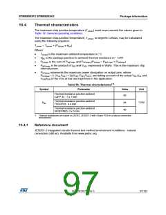
Table 55. Thermal characteristics
Parameter
Symbol
Value
Unit
Thermal resistance junction-ambient
LQFP 32 - 7 x 7 mm
60
Thermal resistance junction-ambient
TSSOP20 - 4.4 mm
Θ
84
90
°C/W
JA
Thermal resistance junction-ambient
UFQFPN20 -3 x 3 mm
1. Thermal resistances are based on JEDEC JESD51-2 with 4-layer PCB in a natural convection
environment.
10.4.1
Reference document
JESD51-2 integrated circuits thermal test method environment conditions - natural
convection (still air). Available from www.jedec.org.
DocID018576 Rev 5
97/103
98

 STMICROELECTRONICS [ ST ]