STM32F103x8, STM32F103xB
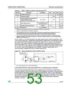
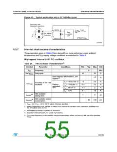
Figure 25. Typical application with a 32.768 kHz crystal
Electrical characteristics
Resonator with
integrated capacitors
C
L1
f
OSC32_IN
LSE
Bias
controlled
gain
32.768 kHz
resonator
R
F
STM32F103xx
OSC32_OUT
C
L2
ai14146
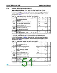
5.3.7
Internal clock source characteristics
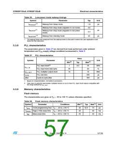
The parameters given in Table 24 are derived from tests performed under ambient
temperature and V supply voltage conditions summarized in Table 9.
DD
High-speed internal (HSI) RC oscillator
(1)
Table 24. HSI oscillator characteristics
Symbol
Parameter
Frequency
Conditions
Min
Typ Max Unit
fHSI
8
MHz
%
DuCy(HSI) Duty cycle
45
55
User-trimmed with the RCC_CR
register(2)
1(3)
%
TA = –40 to 105 °C
–2
2.5
2.2
2
%
%
%
%
Accuracy of the HSI
oscillator
ACCHSI
Factory-
TA = –10 to 85 °C
–1.5
–1.3
–1.1
calibrated
(4)(5)
TA = 0 to 70 °C
TA = 25 °C
1.8
HSI oscillator
startup time
(4)
tsu(HSI)
1
2
µs
HSI oscillator power
consumption
(4)
IDD(HSI)
80
100
µA
1.
VDD = 3.3 V, TA = –40 to 105 °C unless otherwise specified.
2. Refer to application note AN2868 “STM32F10xxx internal RC oscillator (HSI) calibration” available from
the ST website www.st.com.
3. Guaranteed by design, not tested in production.
4. Based on characterization, not tested in production.
5. The actual frequency of HSI oscillator may be impacted by a reflow, but does not drift out of the specified
range.
Doc ID 13587 Rev 15
55/105

 STMICROELECTRONICS [ ST ]