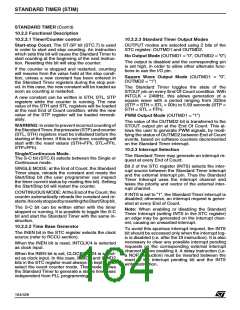
STANDARD TIMER (STIM)
STANDARD TIMER (Cont’d)
10.2.4 Register Description
COUNTER HIGH BYTE REGISTER (STH)
R240 - Read/Write
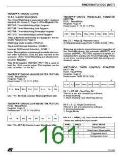
STANDARD TIMER CONTROL REGISTER
(STC)
Register Page: 11
R243 - Read/Write
Reset value: 1111 1111 (FFh)
Register Page: 11
Reset value: 0001 0100 (14h)
7
0
7
0
ST.15 ST.14 ST.13 ST.12 ST.11 ST.10 ST.9
ST.8
S-C INMD1 INMD2 INEN INTS OUTMD1 OUTMD2
ST-SP
Bits 7:0 = ST.[15:8]: Counter High-Byte.
Bit 7 = ST-SP: Start-Stop Bit.
This bit is set and cleared by software.
0: Stop counting
COUNTER LOW BYTE REGISTER (STL)
R241 - Read/Write
Register Page: 11
Reset value: 1111 1111 (FFh)
1: Start counting
Bit 6 = S-C: Single-Continuous Mode Select.
This bit is set and cleared by software.
0: Continuous Mode
7
0
1: Single Mode
ST.7
ST.6
ST.5
ST.4
ST.3
ST.2
ST.1
ST.0
Bits 7:0 = ST.[7:0]: Counter Low Byte.
Bits 5:4 = INMD[1:2]
Bit 3 = INEN
Writing to the STH and STL registers allows the
user to enter the standard timer constant from 1
(0000h) to 65536 (FFFFh). Reading these regis-
ters provides the counter's current value. Thus it is
possible to read the counter on-the-fly.
These 3 bits select the clock source.
INMD1 INMD2 INEN Clock input
0
X
0
X
1
0
CLOCK2/1024
INTCLK/4
STANDARD TIMER PRESCALER REGISTER
(STP)
Bit 2 = INTS: Interrupt Selection.
0: Standard Timer interrupt enabled
1: Standard Timer interrupt is disabled and the ex-
ternal interrupt pin is enabled.
R242 - Read/Write
Register Page: 11
Reset value: 1111 1111 (FFh)
7
0
Bits 1:0 = OUTMD[1:2]: Output Mode Selection.
These bits select the output functions as described
in Section 10.2.2.3.
STP.7 STP.6 STP.5 STP.4 STP.3 STP.2 STP.1 STP.0
OUTMD1 OUTMD2 Mode
Bits 7:0 = STP.[7:0]: Prescaler.
0
0
1
0
1
x
No output mode
The Prescaler value for the Standard Timer is pro-
grammed into this register. When reading the STP
register, the returned value corresponds to the
programmed data instead of the current data.
00h: No prescaler
Square wave output mode
PWM output mode
01h: Divide by 2
FFh: Divide by 256
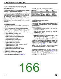
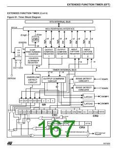
165/426
9

 STMICROELECTRONICS [ ST ]