M93C86, M93C76, M93C66, M93C56, M93C46
Table 12. AC Measurement Conditions (M93Cx6)
Symbol
Parameter
Min.
Max.
Unit
pF
ns
V
C
Load Capacitance
100
L
Input Rise and Fall Times
50
Input Pulse Voltages
0.4 V to 2.4 V
1.0 V and 2.0 V
0.8 V and 2.0 V
Input Timing Reference Voltages
Output Timing Reference Voltages
V
V
Note: 1. Output Hi-Z is defined as the point where data out is no longer driven.
Table 13. AC Measurement Conditions (M93Cx6-W and M93Cx6-R)
Symbol
Parameter
Min.
Max.
Unit
pF
ns
V
C
Load Capacitance
100
L
Input Rise and Fall Times
50
0.2V to 0.8V
Input Pulse Voltages
CC
CC
CC
CC
0.3V to 0.7V
Input Timing Reference Voltages
Output Timing Reference Voltages
V
CC
0.3V to 0.7V
V
CC
Note: 1. Output Hi-Z is defined as the point where data out is no longer driven.
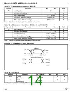
Figure 8. AC Testing Input Output Waveforms
M93CXX
2.4V
2V
2.0V
0.8V
1V
0.4V
INPUT
OUTPUT
M93CXX-W & M93CXX-R
0.8V
0.2V
CC
0.7V
CC
0.3V
CC
CC
AI02553
Table 14. Capacitance
Symbol
Parameter
Test Condition
= 0V
Min
Max
Unit
COUT
Output
Capacitance
5
pF
V
OUT
CIN
Input
Capacitance
5
pF
V
= 0V
IN
Note: Sampled only, not 100% tested, at T =25°C and a frequency of 1MHz.
A
14/31

 STMICROELECTRONICS [ ST ]