L7800
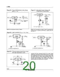
Figure 30 : Power AM Modulator (unity voltage
Figure 31 : Adjustable Output Voltage with
gain, Io < 1A).
TemperatureCompensation.
R 2
R 1
VO = V XX (1 +
) + V
BE
NOTE: The circuit performs well up to 100KHz
NOTE: Q2 is connected as a diode in order to compensate the
variation of the Q1 VBE with the temperature. C allows a slow rise-
time of the Vo
Figure 32 : Light Controllers (Vo min = Vxx + VBE).
VO rises when the light goes up
VO falls when the light goes up
Figure 33 : Protection against Input Short-circuit
with High Capacitance Loads.
Application with high capacitance loads and an output voltage
greater than 6 volts need an external diode (see fig. 33) to protect
the deviceagainst input short circuit. In this case the input voltage
falls rapidly while the output voltage decrease slowly. The
capacitance dischrges by means of the Base-Emitter junction of
the series pass transistor in the regulator. If the energy is
sufficently high, the transistor may be destroyed. The external
diode by-passes the current from the IC to ground.
20/25

 STMICROELECTRONICS [ ST ]