L6699
List of figures
List of figures
Figure 1.
Figure 2.
Figure 3.
Figure 4.
Figure 5.
Figure 6.
Figure 7.
Figure 8.
Figure 9.
Block diagram. . . . . . . . . . . . . . . . . . . . . . . . . . . . . . . . . . . . . . . . . . . . . . . . . . . . . . . . . . . . 1
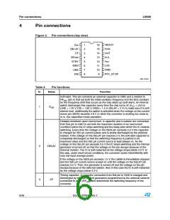
Pin connections (top view) . . . . . . . . . . . . . . . . . . . . . . . . . . . . . . . . . . . . . . . . . . . . . . . . . . 6
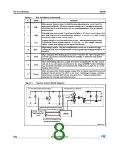
Typical system block diagram. . . . . . . . . . . . . . . . . . . . . . . . . . . . . . . . . . . . . . . . . . . . . . . . 8
Multimode operation of the L6699 . . . . . . . . . . . . . . . . . . . . . . . . . . . . . . . . . . . . . . . . . . . 12
Oscillator's internal block diagram . . . . . . . . . . . . . . . . . . . . . . . . . . . . . . . . . . . . . . . . . . . 13
Oscillator waveforms and their relationship with gate-driving signals. . . . . . . . . . . . . . . . . 14
Adaptive deadtime: principle schematic . . . . . . . . . . . . . . . . . . . . . . . . . . . . . . . . . . . . . . . 16
Relevant timing diagrams . . . . . . . . . . . . . . . . . . . . . . . . . . . . . . . . . . . . . . . . . . . . . . . . . . 16
Detailed view of deadtime during low-to-high transition of half bridge midpoint . . . . . . . . . 16
Figure 10. Comparison startup behavior: traditional controller (left), with L6699 (right) . . . . . . . . . . . 18
Figure 11. Comparison of initial cycles after startup: traditional controller (left), with L6699 (right). . . 19
Figure 12. Soft-start circuit. . . . . . . . . . . . . . . . . . . . . . . . . . . . . . . . . . . . . . . . . . . . . . . . . . . . . . . . . . 20
Figure 13. Input impedance vs. frequency curve in an LLC resonant half bridge . . . . . . . . . . . . . . . . 20
Figure 14. Narrow input voltage range. . . . . . . . . . . . . . . . . . . . . . . . . . . . . . . . . . . . . . . . . . . . . . . . . 21
Figure 15. Wide input voltage range . . . . . . . . . . . . . . . . . . . . . . . . . . . . . . . . . . . . . . . . . . . . . . . . . . 21
Figure 16. Load-dependent operating modes: timing diagram . . . . . . . . . . . . . . . . . . . . . . . . . . . . . . 22
Figure 17. How the L6699 can switch off a PFC controller at light load . . . . . . . . . . . . . . . . . . . . . . . 23
Figure 18. Current sensing techniques with sense resistor . . . . . . . . . . . . . . . . . . . . . . . . . . . . . . . . . 24
Figure 19. Current sensing techniques “lossless”, with capacitive shunt. . . . . . . . . . . . . . . . . . . . . . . 24
Figure 20. Soft-start and delayed shutdown upon overcurrent timing diagram
(safe-start details are not shown) . . . . . . . . . . . . . . . . . . . . . . . . . . . . . . . . . . . . . . . . . . . . 27
Figure 21. Details of hard-switching transition during capacitive-mode operation. . . . . . . . . . . . . . . . 28
Figure 22. Line sensing function: internal block diagram and timing diagram . . . . . . . . . . . . . . . . . . . 31
Figure 23. Bootstrap supply: standard circuit. . . . . . . . . . . . . . . . . . . . . . . . . . . . . . . . . . . . . . . . . . . . 33
Figure 24. Bootstrap supply: internal bootstrap synchronous diode . . . . . . . . . . . . . . . . . . . . . . . . . . 33
Figure 25. SO16N dimensions. . . . . . . . . . . . . . . . . . . . . . . . . . . . . . . . . . . . . . . . . . . . . . . . . . . . . . . 34
Figure 26. Package drawing . . . . . . . . . . . . . . . . . . . . . . . . . . . . . . . . . . . . . . . . . . . . . . . . . . . . . . . . 35
Figure 27. Recommended footprint (dimensions are in mm). . . . . . . . . . . . . . . . . . . . . . . . . . . . . . . . 36
Doc ID 022835 Rev 2
3/38

 STMICROELECTRONICS [ ST ]