L6699
Application information
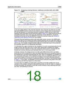
6.2
Adaptive deadtime
A deadtime TD inserted between the turn-off of either switch and the turn-on of the
complementary one, where both switches are in the OFF-state, is essential to achieve soft-
switching. Its value must be larger than the time TT needed for the rail-to-rail swing of the
half bridge midpoint. This duration TT depends on the total parasitic capacitance of the half
bridge midpoint, which must be completely charged or depleted and the value of the
resonant tank current during the transition.
With good approximation, the tank current during the transition time TT can be considered
constant and equal to the “switched current” IS, i.e. the value of the tank current as the
transition begins. If CHB denotes the total parasitic capacitance of the half bridge midpoint (it
includes the Coss of the MOSFETs, the transformer's primary winding parasitic
capacitance, plus other stray contributors), the condition for soft-switching is:
Equation 3
CHB
TT =
Vin ≤ TD
IS
which should be met under all operating conditions. This formula suggests that TD should be
large enough to always exceed TT, especially with maximum Vin and at no load, where IS is
at a minimum and TT at a maximum. However, a too long deadtime may lead to the loss of
soft-switching too: in fact, the tank current must not change its sign within the deadtime,
which could lead to the turn-on of either MOSFET with a non-zero drain-to-source voltage
or, even worse, with the body diode of the other MOSFET conducting (capacitive mode
operation - see Section 9: Capacitive-mode detection function for more details). This may
occur at maximum load and minimum Vin, especially when the tank circuit is designed for a
low magnetizing current to optimize light load efficiency. Additionally, a too long deadtime
may increase conduction losses in the body diodes and significantly limit the operating
frequency of the half bridge.
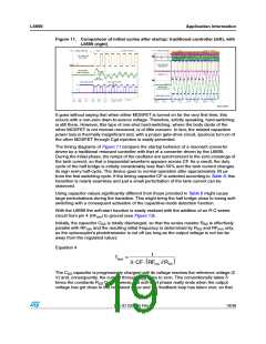
A good approach is to automatically adjust TD so that it tracks TT, keeping TT ≤ TD under all
operating conditions. This is the objective of the adaptive deadtime function in the L6699.
Figure 7 and Figure 8 show the principle schematic and its key waveforms. An edge
detector (the |d/dt| block) senses that the half bridge midpoint (connected to the OUT pin) is
swinging from B+ to GND or vice versa through the VBOOT pin, which moves exactly following
the OUT pin (due to Cboot there is a DC voltage difference between them). The output of
the |d/dt| block is high as long as the OUT pin is swinging and, as the transition is
completed, the output goes low. A monostable circuit, sensitive to negative-going edges,
releases a pulse that marks the end of the deadtime.
Doc ID 022835 Rev 2
15/38

 STMICROELECTRONICS [ ST ]