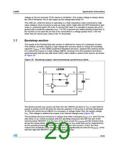
Application information
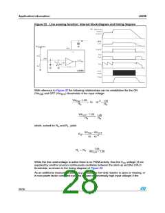
Figure 32. Line sensing function: internal block diagram and timing diagram
L6599
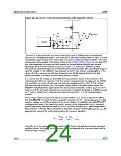
With reference to Figure 32 the following relationships can be established for the ON
(Vin ) and OFF (Vin
) thresholds of the input voltage:
ON
OFF
VinON – 1.25
–6
1.25
RH
----------------------------------
= 15 ⋅ 10 + -----------
RH
VinOFF – 1.25
------------------------------------
1.25
RH
= -----------
RH
which, solved for R and R , yield:
H
L
VinON – VinOFF
RH= ------------------------------------------
15 ⋅ 10–6
1.25
VinOFF – 1.25
------------------------------------
⋅
RL = RH
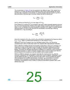
While the line undervoltage is active there is no PWM activity, thus the V voltage (if not
CC
supplied by another source) continuously oscillates between the start-up and the UVLO
thresholds, as shown in the timing diagram of Figure 32.
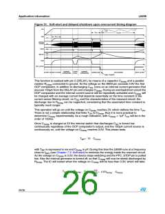
As an additional measure of safety (e.g. in case the low-side resistor is open or missing, or
in non-power factor corrected systems in case of abnormally high input voltage) if the
28/36

 STMICROELECTRONICS [ ST ]