L298
Thissolutioncandriveuntil3 AmpsInDCoperation
and until 3.5 Amps of a repetitivepeak current.
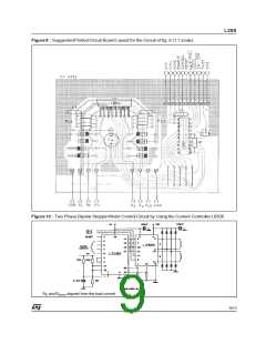
Fig 10 shows a second two phase bipolar stepper
motor control circuit where the current is controlled
by the I.C. L6506.
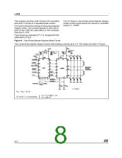
OnFig8itisshownthedrivingofa twophasebipolar
stepper motor ; the needed signals to drive the in-
puts of the L298 are generated, in this example,
from the IC L297.
Fig 9 showsan exampleof P.C.B. designedforthe
application of Fig 8.
Figure 8 :
Two Phase Bipolar Stepper MotorCircuit.
This circuit drives bipolar steppermotorswith winding currents up to 2 A. The diodesare fast 2 A types.
RS1 = RS2 = 0.5
Ω
VF ≤ 1.2 V @ I = 2 A
D1 to D8 = 2 A Fast diodes
{
trr 200 ns
≤
8/13

 STMICROELECTRONICS [ ST ]