L296 - L296P
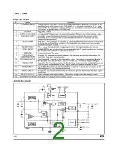
PIN FUNCTIONS
N
°
Name
Function
1
CROWBAR INPUT
Voltage Sense Input for Crowbar Overvoltage Protection. Normally connected to the
feedback input thus triggering the SCR when V out exceeds nominal by 20 %. May
also monitor the input and a voltage divider can be added to increase the threshold.
Connected to ground when SCR not used.
2
3
4
OUTPUT
Regulator Output
SUPPLY VOLTAGE Unrergulated Voltage Input. An internal Regulator Powers the L296s Internal Logic.
CURRENT LIMIT
A resistor connected between this terminal and ground sets the current limiter
threshold. If this terminal is left unconnected the threshold is internally set (see
electrical characteristics).
5
SOFT START
Soft Start Time Constant. A capacitor is connected between this terminal and ground
to define the soft start time constant. This capacitor also determines the average
short circuit output current.
6
7
INHIBIT INPUT
SYNC INPUT
TTL – Level Remote Inhibit. A logic high level on this input disables the device.
Multiple L296s are synchronized by connecting the pin 7 inputs together and omitting
the oscillator RC network on all but one device.
8
9
GROUND
Common Ground Terminal
FREQUENCY
COMPENSATION
A series RC network connected between this terminal and ground determines the
regulation loop gain characteristics.
10
11
12
13
14
FEEDBACK INPUT
The Feedback Terminal on the Regulation Loop. The output is connected directly to
this terminal for 5.1V operation ; it is connected via a divider for higher voltages.
OSCILLATOR
A parallel RC networki connected to this terminal determines the switching frequency.
This pin must be connected to pin 7 input when the internal oscillator is used.
RESET INPUT
RESET DELAY
RESET OUTPUT
Input of the Reset Circuit. The threshold is roughly 5 V. It may be connected to the
feedback point or via a divider to the input.
A capacitor connected between this terminal and ground determines the reset signal
delay time.
Open collector reset signal output. This output is high when the supply is safe.
15 CROWBAR OUTPUT SCR gate drive output of the crowbar circuit.
BLOCK DIAGRAM
2/22

 STMICROELECTRONICS [ ST ]