L200
(continued)
ELECTRICAL CHARACTERISTICS
Symbol
Parameter
Test Conditions
Min.
Typ.
Max.
Unit
mV/ C
Vi = 20 V Io = 10mA
V
∆
Average Temperature Coefficient
of Reference Voltage
ref
for Tj = - 25 to 125 C
for Tj = 125 to 150 C
-0.25
-1.5
°
°
°
mV/ C
°
I4
∆ I4
Bias Current and Pin 4
3
10
A
µ
Average Temperature
Coefficient (pin 4)
-0.5
%/°C
T
∆
• I4
Zo
Output Impedance
Vi = 10 V
Io = 0.5 A
Vo = Vref
f = 100 Hz
1.5
mΩ
CURRENT REGULATION LOOP
VSC
Current Limit Sense Voltage
between Pins 5 and 2
Vi = 10 V
I5 = 100 mA
Vo = Vref
0.38
0.45
0.03
0.52
V
V
∆
SC
Average Temperature
Coefficient of VSC
%/°
C
T
VSC
∆
•
I
∆
o
Current Load Regulation
Vi = 10 V
Io = 0.5 A
Io = 1A
∆Vo = 3V
1.4
1
0.9
%
%
%
Io
Io = 1.5 A
ISC
Peak Short Circuit Current
Vi - V0 = 14 V
(pins 2 and 5 short circuited)
3.6
A
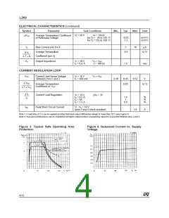
Note 1: A load step of 2 A can be applied provited that input-output differential voltage is lower than 20 V (see Figure 3).
Note 2: The same performance can be maintained at higher output levels if a bypassing capacitor is provited between pins 2 and 4.
Figure 3. Typical Safe Operating Area
Protection.
Figure 4. Quiescent Current vs. Supply
Voltage.
4/12

 STMICROELECTRONICS [ ST ]