HCC/HCF4098B
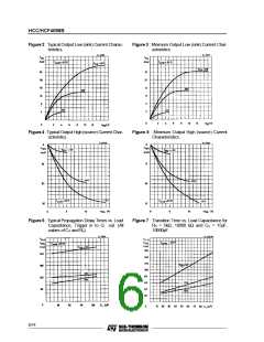
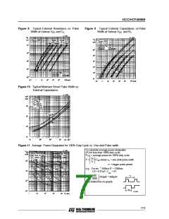
Figure 8 : Typical External Resistance vs. Pulse
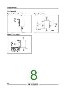
Figure 9 : Typical External Capacitance vs.Pulse
Width at Various VDD and CX.
Width at Various VDD and RX.
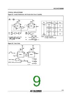
Figure 10 : Typical Minimum Reset Pulse Width vs.
External Capacitance.
Figure 11 : Average Power Dissipation for 100% Duty Cycle vs. One-shot Pulse width.
To calculate average power dissipation
(P) for less than 100% duty cycle :
P100 = average power for 100% duty cycle
τm
P =
P100 where τm = one-shot pulse width
τT
τT = trigger pulse period
=
e.g. : For tm … 600ms tT = 1000ms,
CX = 0.01µF, V = 5V
DD
600
P =
103µW = 600µW
1000
(see dotted line on graph)
7/14

 STMICROELECTRONICS [ ST ]