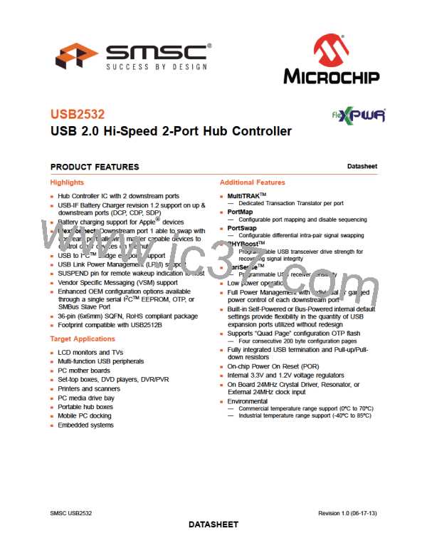
USB 2.0 Hi-Speed 2-Port Hub Controller
Datasheet
8.2
Flex Connect
This feature allows the upstream port to be swapped with downstream physical port 1. Only
downstream port 1 can be swapped physically. Using port remapping, any logical port (number
assignment) can be swapped with the upstream port (non-physical).
Flex Connect is enabled/disabled via two control bits in the Connect Configuration Register. The
FLEXCONNECT configuration bit switches the port, and EN_FLEX_MODE enables the mode.
8.2.1
Port Control
Once EN_FLEX_MODE bit is set, the functions of certain pins change, as outlined below.
If EN_FLEX_MODE is set and FLEXCONNECT is not set:
1. PRTPWR1 enters combined mode, becoming PRTPWR1/OCS1_N
2. OCS1_N becomes a don’t care
3. SUSPEND outputs ‘0’ to keep any upstream power controller off
If EN_FLEX_MODE is set and FLEXCONNECT is set:
1. The normal upstream VBUS pin becomes a don’t care
2. PRTPWR1 is forced to a ‘1’ in combined mode, keeping the port power on to the application
processor.
3. OCS1 becomes VBUS from the application processor through a GPIO
4. SUSPEND becomes PRTPWR1/OCS1_N for the port power controller for the connector port
8.3
Resets
The device has the following chip level reset sources:
Power-On Reset (POR)
External Chip Reset (RESET_N)
USB Bus Reset
8.3.1
8.3.2
Power-On Reset (POR)
A power-on reset occurs whenever power is initially supplied to the device, or if power is removed and
reapplied to the device. A timer within the device will assert the internal reset per the specifications
listed in Section 9.5.1, "Power-On Configuration Strap Valid Timing," on page 55.
External Chip Reset (RESET_N)
A valid hardware reset is defined as assertion of RESET_N, after all power supplies are within
operating range, per the specifications in Section 9.5.2, "Reset and Configuration Strap Timing," on
page 56. While reset is asserted, the device (and its associated external circuitry) enters Standby Mode
and consumes minimal current.
Assertion of RESET_N causes the following:
1. The PHY is disabled and the differential pairs will be in a high-impedance state.
2. All transactions immediately terminate; no states are saved.
3. All internal registers return to the default state.
SMSC USB2532
47
Revision 1.0 (06-17-13)
DATASHEET

 SMSC [ SMSC CORPORATION ]