USB 2.0 Hi-Speed 2-Port Hub Controller
Datasheet
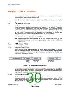
In this operation, following the 7-bit slave address, the 8-bit register address is written indicating the
start address for the subsequent sequential read operation. In the read sequence, every data access
is a data read from a data register where the register address increments after each access. The write
sequence can end with optional Stop (P). If so, the read sequence must begin with a Start (S).
Otherwise, the read sequence must start with a Repeated Start (Sr).
Figure 7.2 shows the format of the read operation. Where color is visible in the figure, blue and gold
indicate signaling from the I2C master, and gray indicates signaling from the slave.
Optional. If present, Next
access must have Start(S),
otherwise Repeat Start (Sr)
S
7-Bit Slave Address
0
A
xxxxxxxx
A
P
Register
Address
(bits 7-0)
If previous write setting up
Register address ended with a
Stop (P), otherwise it will be
Repeated Start (Sr)
S
7-Bit Slave Address
1
ACK n n n n n n n n ACK n n n n n n n n ACK
...
n n n n n n n n NACK
P
Register value
for xxxxxxxx
Register value
for xxxxxxxx + 1
Register value
for xxxxxxxx + y
Figure 7.2 I2C Sequential Access Read Format
2
7.1.2
Pull-Up Resistors for I C
The circuit board designer is required to place external pull-up resistors (10 kΩ recommended) on the
SDA & SCL signals (per SMBus 1.0 Specification) to Vcc in order to assure proper operation.
7.2
SMBus Slave Interface
The USB2532 includes an integrated SMBus slave interface, which can be used to access internal
device run time registers or program the internal OTP memory. SMBus detection is accomplished by
detection of pull-up resistors (10 KΩ recommended) on both the SMBDATA and SMBCLK signals. To
disable the SMBus, a pull-down resistor of 10 KΩ must be applied to SMBDATA. The SMBus interface
can be used to configure the device as detailed in Section 6.1, "Configuration Method Selection," on
page 25.
Note: All device configuration must be performed via the SMSC Pro-Touch Programming Tool. For
additional information on the Pro-Touch programming tool, contact your local SMSC sales
representative.
7.2.1
SMBus Run Time Accessible Registers
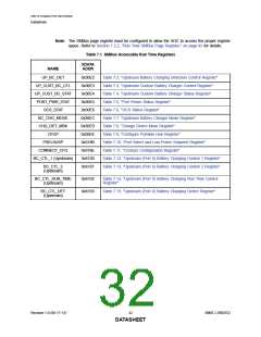
Table 7.1 provides a summary of the SMBus accessible run time registers. Each register is detailed in
the subsequent tables.
SMSC USB2532
31
Revision 1.0 (06-17-13)
DATASHEET

 SMSC [ SMSC CORPORATION ]