USB 2.0 Hi-Speed 2-Port Hub Controller
Datasheet
5.1
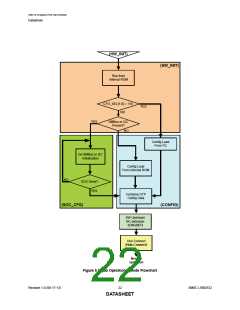
Boot Sequence
5.1.1
Standby Mode
If the external hardware reset is asserted, the hub will be in Standby Mode. This mode provides a very
low power state for maximum power efficiency when no signaling is required. This is the lowest power
state. In Standby Mode all internal regulators are powered off, the PLL is not running, and core logic
is powered down in order to minimize power consumption. Because core logic is powered off, no
configuration settings are retained in this mode and must be re-initialized after RESET_N is negated
high.
5.1.2
Hardware Initialization Stage (HW_INIT)
The first stage is the initialization stage and occurs on the negation of RESET_N. In this stage the
1.2V regulator is enabled and stabilizes, internal logic is reset, and the PLL locks if a valid REFCLK
is supplied. Configuration registers are initialized to their default state and strap input values are
latched. The device will complete initialization and automatically enter the next stage. Because the
digital logic within the device is not yet stable, no communication with the device using the SMBus is
possible. Configuration registers are initialized to their default state.
If there is a REFCLK present, the next state is SW_INIT.
5.1.3
Software Initialization Stage (SW_INIT)
Once the hardware is initialized, the firmware can begin to execute from the internal ROM. The
firmware checks the CFG_SEL[1:0] configuration strap values to determine if it is configured for I2C
Master loading. If so, the configuration is loaded from an external I2C ROM in the device’s CONFIG
state.
For all other configurations, the firmware checks for the presence of an external I2C/SMBus. It does
this by asserting two pull down resistors on the data and clock lines of the bus. The pull downs are
typically 50Kohm. If there are 10Kohm pull-ups present, the device becomes aware of the presence
of an external SMBus/I2C bus. If a bus is detected, the firmware transitions to the SOC_CFG state.
5.1.4
5.1.5
SOC Configuration Stage (SOC_CFG)
In this stage, the SOC may modify any of the default configuration settings specified in the integrated
ROM such as USB device descriptors, or port electrical settings, and control features such as
upstream battery charging detection.
There is no time limit. In this stage the firmware will wait indefinitely for the SMBus/I2C configuration.
When the SOC has completed configuring the device, it must write to register 0xFF to end the
configuration.
Configuration Stage (CONFIG)
Once the SOC has indicated that it is done with configuration, then all the configuration data is
combined. The default data, the SOC configuration data, the OTP data are all combined in the firmware
and device is programmed.
After the device is fully configured, it will go idle and then into suspend if there is no VBUS or
Hub.Connect present. Once VBUS is present, and upstream battery charging is enabled, the device
will transition to the Battery Charger Detection Stage (CHGDET). If VBUS is present, and upstream
battery charging is not enabled, the device will transitions to the Connect (Hub.Connect) stage.
SMSC USB2532
23
Revision 1.0 (06-17-13)
DATASHEET

 SMSC [ SMSC CORPORATION ]