FIFO POLLED MODE OPERATION
With FCR bit 0 = "1" resetting IER bits 0, 1, 2 or 3 or all to zero puts the UART in the FIFO Polled Mode of operation.
Since the RCVR and XMITTER are controlled separately, either one or both can be in the polled mode of operation. In
this mode, the user's program will check RCVR and XMITTER status via the LSR. LSR definitions for the FIFO Polled
Mode are as follows:
ꢀ
ꢀ
Bit 0=1 as long as there is one byte in the RCVR FIFO.
Bits 1 to 4 specify which error(s) have occurred. Character error status is handled the same way as when
in the interrupt mode, the IIR is not affected since EIR bit 2=0.
Bit 5 indicates when the XMIT FIFO is empty.
ꢀ
ꢀ
ꢀ
Bit 6 indicates that both the XMIT FIFO and shift register are empty.
Bit 7 indicates whether there are any errors in the RCVR FIFO.
There is no trigger level reached or timeout condition indicated in the FIFO Polled Mode, however, the RCVR and XMIT
FIFOs are still fully capable of holding characters.
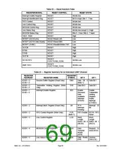
Table 31 – Baud Rates
DESIRED
BAUD RATE
50
DIVISOR USED TO
PERCENT ERROR DIFFERENCE
HIGH
GENERATE 16X CLOCK
BETWEEN DESIRED AND ACTUAL1
SPEED BIT2
2304
1536
1047
857
768
384
192
96
0.001
X
X
X
X
X
X
X
X
X
X
X
X
X
X
X
X
X
X
X
1
75
-
-
110
134.5
150
0.004
-
300
-
600
-
1200
-
1800
64
-
2000
58
0.005
2400
48
-
3600
32
-
-
4800
24
7200
16
-
9600
12
-
19200
38400
57600
115200
230400
460800
6
-
3
0.030
0.16
0.16
0.16
0.16
2
1
32770
32769
1
Note1: The percentage error for all baud rates, except where indicated otherwise, is 0.2%.
Note 2: The High Speed bit is located in the Device Configuration Space.
SMSC DS – LPC47M14X
Page 68
Rev. 03/19/2001

 SMSC [ SMSC CORPORATION ]