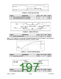
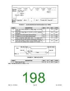
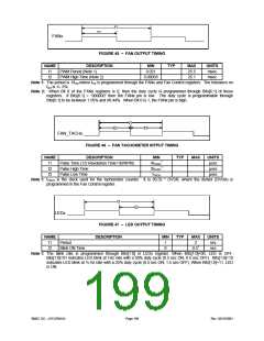
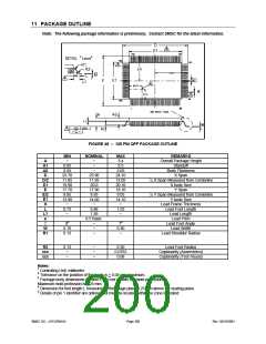
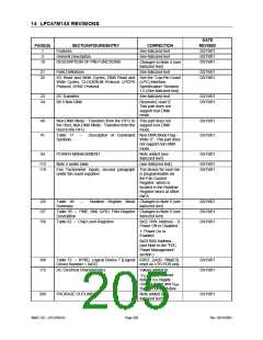
12 APPENDIX - TEST MODE
12.1 BOARD TEST MODE
Board test mode can be entered as follows:
On the rising (deasserting) edge of PCI_RESET#, drive LFRAME# low and drive LAD[0] low.
Exit board test mode as follows:
On the rising (deasserting) edge of PCI_RESET#, drive either LFRAME# or LAD[0] high.
See the “XNOR-Chain Test Mode” section below for a description of this board test mode.
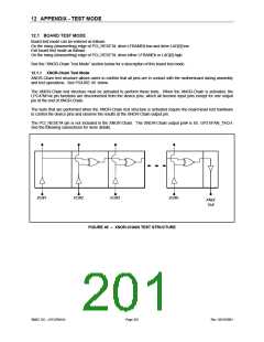
12.1.1 XNOR-Chain Test Mode
XNOR-Chain test structure allows users to confirm that all pins are in contact with the motherboard during assembly
and test operations. See FIGURE 49 below.
The XNOR-Chain test structure must be activated to perform these tests. When the XNOR-Chain is activated, the
LPC47M14x pin functions are disconnected from the device pins, which all become input pins except for one output
pin at the end of XNOR-Chain.
The tests that are performed when the XNOR-Chain test structure is activated require the board-level test hardware
to control the device pins and observe the results at the XNOR-Chain output pin.
The PCI_RESET# pin is not included in the XNOR-Chain. The XNOR-Chain output pin# is 85, GP31/FAN_TACH.
See the following subsections for more details.
I/O#1
I/O#2
I/O#3
I/O#n
XNor
Out
FIGURE 49 – XNOR-CHAIN TEST STRUCTURE
SMSC DS – LPC47M14X
Page 201
Rev. 03/19/2001

 SMSC [ SMSC CORPORATION ]