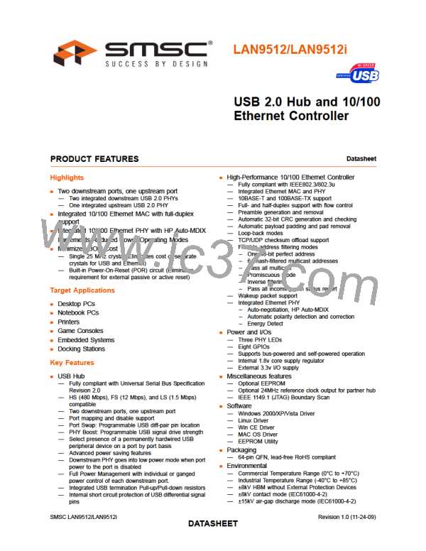
USB 2.0 Hub and 10/100 Ethernet Controller
Datasheet
Table 3.8 Boost_3:2 Register (BOOST32) Format (continued)
BITS
DESCRIPTION
DEFAULT
3:2
Upstream USB Electrical Signaling Drive Strength Boost Bit for
Downstream Port 2 (BOOST_IOUT_2)
00b
00 = Normal electrical drive strength
01 = Elevated electrical drive strength (+4% boost)
10 = Elevated electrical drive strength (+8% boost)
11 = Elevated electrical drive strength (+12% boost)
1:0
RESERVED
00b
Table 3.9 Status/Command Register (STCD) Format
BITS
7:2
1
DESCRIPTION
DEFAULT
000000b
0b
RESERVED
Reset (RESET)
Resets the internal memory back to nRESET assertion default settings.
0 = Normal Run/Idle State
1 = Force a reset of the registers to their default state
Note:
During this reset, this bit is automatically cleared to its default value
of 0.
0
USB Attach and Write Protect (USB_ATTACH)
1b
0 = Device is in configuration state
1 = Hub will signal a USB attach event to an upstream device, and the
internal memory (address range 00h - FEh) is “write-protected” to prevent
unintentional data corruption.
Note:
This bit is write once and is only cleared by assertion of the external
nRESET or POR.
SMSC LAN9512/LAN9512i
Revision 1.0 (11-24-09)
DATA3S1HEET

 SMSC [ SMSC CORPORATION ]