High Performance Single-Chip 10/100 Non-PCI Ethernet Controller
Datasheet
EEPROM Write
EEPROM Read
Idle
Idle
Write
Command
Register
Write Data
Register
Write
Read
Command
Register
Command
Register
Busy Bit = 0
Read
Read Data
Register
Command
Busy Bit = 0
Register
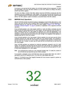
Figure 3.3 EEPROM Access Flow Diagram
The host can disable the EEPROM interface through the GPIO_CFG register. When the interface is
disabled, the EEDIO and ECLK signals can be used as general-purpose outputs, or they may be used
to monitor internal MII signals.
3.9.2.1
Supported EEPROM Operations
The EEPROM controller supports the following EEPROM operations under host control via the
E2P_CMD register. The operations are commonly supported by “93C46” EEPROM devices. A
description and functional timing diagram is provided below for each operation. Please refer to the
E2P_CMD register description in Section 5.3.23, "E2P_CMD – EEPROM Command Register," on
page 94 for E2P_CMD field settings for each command.
ERASE (Erase Location): If erase/write operations are enabled in the EEPROM, this command will
erase the location selected by the EPC Address field (EPC_ADDR). The EPC_TO bit is set if the
EEPROM does not respond within 30ms.
SMSC LAN9117
Revision 1.1 (05-17-05)
DATA3S3HEET

 SMSC [ SMSC CORPORATION ]