Highly Efficient Single-Chip 10/100 Non-PCI Ethernet Controller
Datasheet
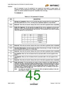
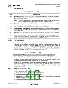
TX COMMAND ‘B’
Table 3.12 TX Command 'B' Format
DESCRIPTION
BITS
31:16
Packet Tag. The host should write a unique packet identifier to this field. This identifier is added to
the corresponding TX status word and can be used by the host to correlate TX status words with
their corresponding packets.
Note:
The use of packet tags is not required by the hardware. This field can be used by the LAN
software driver for any application. Packet Tags is one application example.
15:14
13
Reserved. These bits are reserved. Always write zeros to this field to guarantee future compatibility.
Add CRC Disable. When set, the automatic addition of the CRC is disabled.
12
Disable Ethernet Frame Padding. When set, this bit prevents the automatic addition of padding to
an Ethernet frame of less than 64 bytes. The CRC field is also added despite the state of the Add
CRC Disable field.
11
Reserved. These bits are reserved. Always write zeros to this field to guarantee future compatibility.
10:0
Packet Length (bytes). This field indicates the total number of bytes in the current packet. This
length does not include the offset or padding. If the Packet Length field does not match the actual
number of bytes in the packet the Transmitter Error (TXE) flag will be set.
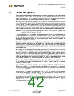
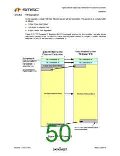
3.12.3
TX Data Format
The TX data section begins at the third DWORD in the TX buffer (after TX command ‘A’ and TX
command ‘B’). The location of the first byte of valid buffer data to be transmitted is specified in the
“Data Start Offset” field of the TX command ‘A’ word. Table 3.13, "TX DATA Start Offset", shows the
correlation between the setting of the LSB’s in the “Data Start Offset” field and the byte location of the
first valid data byte. Additionally, transmit buffer data can be offset by up to 7 additional DWORDS as
indicated by the upper three MSB’s (5:2) in the “Data Start Offset” field.
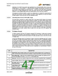
Table 3.13 TX DATA Start Offset
Data Start Offset [1:0]:
First TX Data Byte:
11
D[31:24]
10
D[23:16]
01
D[15:8]
00
D[7:0]
TX data is contiguous until the end of the buffer. The buffer may end on a byte boundary. Unused
bytes at the end of the packet will not be sent to the MIL for transmission.
The Buffer End Alignment field in TX command ‘A’ specifies the alignment that must be maintained for
the associated buffer. End alignment may be specified as 4-, 16-, or 32-byte. The host processor is
responsible for adding the additional data to the end of the buffer. The hardware will automatically
remove this extra data.
3.12.3.1
TX Buffer Fragmentation Rules
Transmit buffers must adhere to the following rules:
■
■
■
Each buffer can start and end on any arbitrary byte alignment
The first buffer of any transmit packet can be any length
Middle buffers (i.e., those with First Segment = Last Segment = 0) must be greater than, or equal
to 4 bytes in length
■
The final buffer of any transmit packet can be any length
Revision 1.1 (05-17-05)
SMSC LAN9116
DATA4S6HEET

 SMSC [ SMSC CORPORATION ]