±15kV ESD Protected MII/RMII 10/100 Ethernet Transceiver with HP Auto-MDIX Support and flexPWR® Technology in a Small Footprint
Datasheet
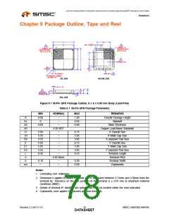
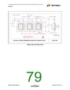
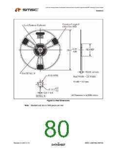
Chapter 9 Package Outline, Tape and Reel
Figure 9.1 36-Pin QFN Package Outline, 6 x 6 x 0.90 mm Body (Lead-Free)
Table 9.1 36-Pin QFN Package Parameters
MIN
NOMINAL
MAX
REMARKS
A
A1
A2
A3
D
0.80
0
~
1.00
0.05
0.80
Overall Package Height
Standoff
~
0.60
~
Mold Thickness
0.20 REF
Copper Lead-frame Substrate
X Overall Size
5.85
5.55
3.55
5.85
5.55
3.55
0.35
~
6.15
5.95
3.85
6.15
5.95
3.85
0.75
D1
D2
E
~
X Mold Cap Size
X exposed Pad Size
Y Overall Size
~
~
E1
E2
L
~
Y Mold Cap Size
Y exposed Pad Size
Terminal Length
Terminal Pitch
~
~
e
0.50 Basic
b
0.18
~
~
~
0.30
0.08
Terminal Width
ccc
Coplanarity
Notes:
1. Controlling Unit: millimeter.
2. Dimension b applies to plated terminals and is measured between 0.15mm and 0.30mm from the
terminal tip. Tolerance on the true position of the terminal is ± 0.05 mm at maximum material
conditions (MMC).
3. Details of terminal #1 identifier are optional but must be located within the zone indicated.
4. Coplanarity zone applies to exposed pad and terminals.
Revision 2.3 (04-12-11)
SMSC LAN8700/LAN8700i
DATA7S8HEET

 SMSC [ SMSC CORPORATION ]