±15kV ESD Protected MII/RMII 10/100 Ethernet Transceiver with HP Auto-MDIX Support and flexPWR® Technology in a Small Footprint
Datasheet
5.4.9
Configuration Signals
The PHY has 11 configuration signals whose inputs should be driven continuously, either by external
logic or external pull-up/pull-down resistors.
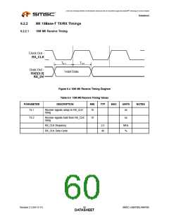
5.4.9.1
Physical Address Bus - PHYAD[4:0]
The PHYAD[4:0] signals are driven high or low to give each PHY a unique address. This address is
latched into an internal register at end of hardware reset. In a multi-PHY application (such as a
repeater), the controller is able to manage each PHY via the unique address. Each PHY checks each
management data frame for a matching address in the relevant bits. When a match is recognized, the
PHY responds to that particular frame. The PHY address is also used to seed the scrambler. In a multi-
PHY application, this ensures that the scramblers are out of synchronization and disperses the
electromagnetic radiation across the frequency spectrum.
5.4.9.2
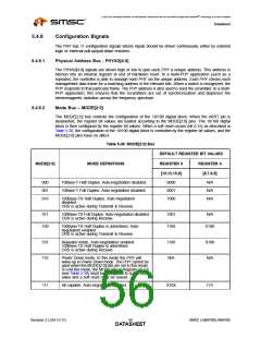
Mode Bus – MODE[2:0]
The MODE[2:0] bus controls the configuration of the 10/100 digital block. When the nRST pin is
deasserted, the register bit values are loaded according to the MODE[2:0] pins. The 10/100 digital
block is then configured by the register bit values. When a soft reset occurs (bit 0.15) as described in
Table 5.30, the configuration of the 10/100 digital block is controlled by the register bit values, and the
MODE[2:0] pins have no affect.
Table 5.48 MODE[2:0] Bus
DEFAULT REGISTER BIT VALUES
MODE[2:0]
MODE DEFINITIONS
REGISTER 0
[13,12,10,8]
REGISTER 4
[8,7,6,5]
000
001
010
10Base-T Half Duplex. Auto-negotiation disabled.
10Base-T Full Duplex. Auto-negotiation disabled.
0000
0001
1000
N/A
N/A
N/A
100Base-TX Half Duplex. Auto-negotiation
disabled.
CRS is active during Transmit & Receive.
011
100
100Base-TX Full Duplex. Auto-negotiation disabled.
CRS is active during Receive.
1001
1100
N/A
100Base-TX Half Duplex is advertised. Auto-
negotiation enabled.
CRS is active during Transmit & Receive.
0100
101
110
Repeater mode. Auto-negotiation enabled.
100Base-TX Half Duplex is advertised.
CRS is active during Receive.
1100
N/A
0100
N/A
Power Down mode. In this mode the PHY will
wake-up in Power-Down mode. The PHY cannot be
used when the MODE[2:0] bits are set to this mode.
To exit this mode, the MODE bits in Register 18.7:5
(see Table 5.39) must be configured to some other
value and a soft reset must be issued.
111
All capable. Auto-negotiation enabled.
X10X
1111
Revision 2.3 (04-12-11)
SMSC LAN8700/LAN8700i
DATA5S6HEET

 SMSC [ SMSC CORPORATION ]