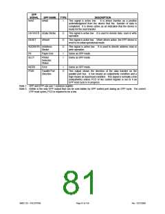
EPP
SIGNAL
EPP NAME
nWait
TYPE
DESCRIPTION
This signal is active low. It is driven inactive as a positive
WAIT
I
acknowledgment from the device that the transfer of data is
completed. It is driven active as an indication that the device is
ready for the next transfer.
DATASTB nData Strobe
RESET nReset
O
O
O
This signal is active low. It is used to denote data read or write
operation.
This signal is active low. When driven active, the EPP device is
reset to its initial operational mode.
This signal is active low. It is used to denote address read or
write operation.
ADDRSTB nAddress
Strobe
PE
SLCT
Paper End
I
I
Same as SPP mode.
Same as SPP mode.
Printer
Selected
Status
NERR
PDIR
Error
Parallel Port
Direction
I
O
Same as SPP mode.
This output shows the direction of the data transfer on the
parallel port bus. A low means an output/write condition and a
high means an input/read condition. This signal is normally a low
(output/write) unless PCD of the control register is set or if an
EPP read cycle is in progress.
Note 1: SPP and EPP can use 1 common register.
Note 2: nWrite is the only EPP output that can be over-ridden by SPP control port during an EPP cycle. For correct
EPP read cycles, PCD is required to be a low.
SMSC DS – FDC37N769
Page 81 of 138
Rev. 12/21/2000

 SMSC [ SMSC CORPORATION ]