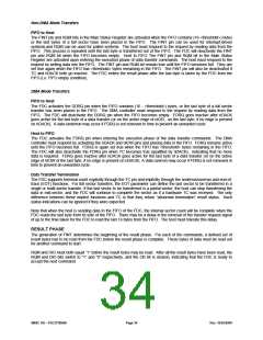
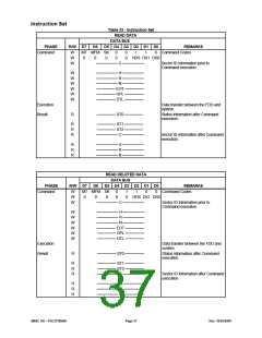
Non-DMA Mode Transfers
FIFO to Host
The FINT pin and RQM bits in the Main Status Register are activated when the FIFO contains (16-<threshold>) bytes
or the last bytes of a full sector have been placed in the FIFO. The FINT pin can be used for interrupt-driven
systems,and RQM can be used for polled systems. The host must respond to the request by reading data from the
FIFO. This process is repeated until the last byte is transferred out of the FIFO. The FDC will deactivate the FINT
pin and RQM bit when the FIFO becomes empty. Host to FIFO The FINT pin and RQM bit in the Main Status
Register are activated upon entering the execution phase of data transfer commands. The host must respond to the
request by writing data into the FIFO. The FINT pin and RQM bit remain true until the FIFO becomes full. They are
set true again when the FIFO has <threshold> bytes remaining in the FIFO. The FINT pin will also be deactivated if
TC and nDACK both go inactive. The FDC enters the result phase after the last byte is taken by the FDC from the
FIFO (i.e. FIFO empty condition).
DMA Mode Transfers
FIFO to Host
The FDC activates the DDRQ pin when the FIFO contains (16 - <threshold>) bytes, or the last byte of a full sector
transfer has been placed in the FIFO. The DMA controller must respond to the request by reading data from the
FIFO. The FDC will deactivate the DDRQ pin when the FIFO becomes empty. FDRQ goes inactive after nDACK
goes active for the last byte of a data transfer (or on the active edge of nIOR, on the last byte, if no edge is present
on nDACK). A data underrun may occur if FDRQ is not removed in time to prevent an unwanted cycle.
Host to FIFO
The FDC activates the FDRQ pin when entering the execution phase of the data transfer commands. The DMA
controller must respond by activating the nDACK and nIOW pins and placing data in the FIFO. FDRQ remains active
until the FIFO becomes full. FDRQ is again set true when the FIFO has <threshold> bytes remaining in the FIFO.
The FDC will also deactivate the FDRQ pin when TC becomes true (qualified by nDACK), indicating that no more
data is required. FDRQ goes inactive after nDACK goes active for the last byte of a data transfer (or on the active
edge of nIOW of the last byte, if no edge is present on nDACK). A data overrun may occur if FDRQ is not removed in
time to prevent an unwanted cycle.
Data Transfer Termination
The FDC supports terminal count explicitly through the TC pin and implicitly through the underrun/overrun and end-of-
track (EOT) functions. For full sector transfers, the EOT parameter can define the last sector to be transferred in a
single or multi-sector transfer. If the last sector to be transferred is a partial sector, the host can stop transferring the
data in mid-sector, and the FDC will continue to complete the sector as if a hardware TC was received. The only
difference between these implicit functions and TC is that they return “abnormal termination” result status. Such
status indications can be ignored if they were expected.
Note that when the host is sending data to the FIFO of the FDC, the internal sector count will be complete when the
FDC reads the last byte from its side of the FIFO. There may be a delay in the removal of the transfer request signal
of up to the time taken for the FDC to read the last 16 bytes from the FIFO. The host must tolerate this delay.
RESULT PHASE
The generation of FINT determines the beginning of the result phase. For each of the commands, a defined set of
result bytes has to be read from the FDC before the result phase is complete. These bytes of data must be read out
for another command to start.
RQM and DIO must both equal “1” before the result bytes may be read. After all the result bytes have been read, the
RQM and DIO bits switch to “1” and “0” respectively, and the CB bit is cleared, indicating that the FDC is ready to
accept the next command.
SMSC DS – FDC37N3869
Page 34
Rev. 10/25/2000

 SMSC [ SMSC CORPORATION ]