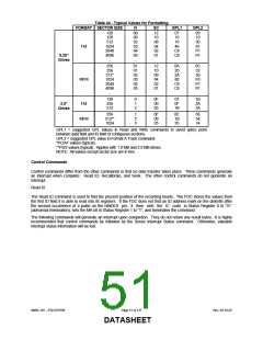
Table 44 - Typical Values for Formatting
FORMAT SECTOR SIZE
N
SC
GPL1
GPL2
128
128
512
1024
2048
4096
...
00
00
02
03
04
05
...
12
10
08
04
02
01
07
10
18
46
C8
C8
09
19
30
87
FF
FF
FM
5.25”
Drives
256
256
01
01
02
03
04
05
...
12
10
09
04
02
01
0A
20
2A
80
C8
C8
0C
32
50
F0
FF
FF
512*
1024
2048
4096
...
MFM
128
256
512
0
1
2
0F
09
05
07
0F
1B
1B
2A
3A
FM
3.5”
Drives
256
512**
1024
1
2
3
0F
09
05
0E
1B
35
36
54
74
MFM
GPL1 = suggested GPL values in Read and Write commands to avoid splice point
between data field and ID field of contiguous sections.
GPL2 = suggested GPL value in Format A Track command.
*PC/AT values (typical)
**PS/2 values (typical). Applies with 1.0 MB and 2.0 MB drives.
NOTE: All values except sector size are in hex.
Control Commands
Control commands differ from the other commands in that no data transfer takes place. Three commands generate
an interrupt when complete: Read ID, Recalibrate, and Seek. The other control commands do not generate an
interrupt.
Read ID
The Read ID command is used to find the present position of the recording heads. The FDC stores the values from
the first ID field it is able to read into its registers. If the FDC does not find an ID address mark on the diskette after
the second occurrence of a pulse on the nINDEX pin, it then sets the IC code in Status Register 0 to “01”
(abnormal termination), sets the MA bit in Status Register 1 to “1”, and terminates the command.
The following commands will generate an interrupt upon completion. They do not return any result bytes. It is highly
recommended that control commands be followed by the Sense Interrupt Status command. Otherwise, valuable
interrupt status information will be lost.
SMSC DS – FDC37N769
Page 51 of 137
Rev. 02-16-07
DATASHEET

 SMSC [ SMSC CORPORATION ]