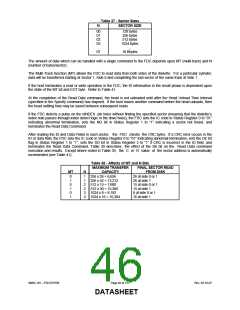
Table 37 - Sector Sizes
SECTOR SIZE
N
00
01
02
03
..
128 bytes
256 bytes
512 bytes
1024 bytes
...
07
16 Kbytes
The amount of data which can be handled with a single command to the FDC depends upon MT (multi-track) and N
(number of bytes/sector).
The Multi-Track function (MT) allows the FDC to read data from both sides of the diskette. For a particular cylinder,
data will be transferred starting at Sector 1, Side 0 and completing the last sector of the same track at Side 1.
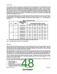
If the host terminates a read or write operation in the FDC, the ID information in the result phase is dependent upon
the state of the MT bit and EOT byte. Refer to Table 41.
At the completion of the Read Data command, the head is not unloaded until after the Head Unload Time Interval
(specified in the Specify command) has elapsed. If the host issues another command before the head unloads, then
the head settling time may be saved between subsequent reads.
If the FDC detects a pulse on the nINDEX pin twice without finding the specified sector (meaning that the diskette’s
index hole passes through index detect logic in the drive twice), the FDC sets the IC code in Status Register 0 to “01”
indicating abnormal termination, sets the ND bit in Status Register 1 to “1” indicating a sector not found, and
terminates the Read Data Command.
After reading the ID and Data Fields in each sector, the FDC checks the CRC bytes. If a CRC error occurs in the
ID or data field, the FDC sets the IC code in Status Register 0 to “01” indicating abnormal termination, sets the DE bit
flag in Status Register 1 to “1”, sets the DD bit in Status Register 2 to “1” if CRC is incorrect in the ID field, and
terminates the Read Data Command. Table 39 describes the effect of the SK bit on the Read Data command
execution and results. Except where noted in Table 39, the C or R value of the sector address is automatically
incremented (see Table 41).
Table 38 - Affects of MT and N Bits
MAXIMUM TRANSFER
CAPACITY
FINAL SECTOR READ
FROM DISK
MT
N
0
1
0
1
0
1
1
1
2
2
3
3
256 x 26 = 6,656
256 x 52 = 13,312
512 x 15 = 7,680
512 x 30 = 15,360
1024 x 8 = 8,192
1024 x 16 = 16,384
26 at side 0 or 1
26 at side 1
15 at side 0 or 1
15 at side 1
8 at side 0 or 1
16 at side 1
SMSC DS – FDC37N769
Page 46 of 137
Rev. 02-16-07
DATASHEET

 SMSC [ SMSC CORPORATION ]