3. Transmitter Holding Register Empty
4. MODEM Status (lowest priority)
Bit 1
Setting this bit to a logic "1" clears all bytes in
the RCVR FIFO and resets its counter logic to 0.
The shift register is not cleared. This bit is self-
clearing.
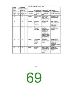
Information indicating that a prioritized interrupt
is pending and the source of that interrupt is
stored in the Interrupt Identification Register
(refer to Interrupt Control Table). When the CPU
accesses the IIR, the Serial Port freezes all
interrupts and indicates the highest priority
pending interrupt to the CPU. During this CPU
access, even if the Serial Port records new
interrupts, the current indication does not
change until access is completed. The contents
of the IIR are described below.
Bit 2
Setting this bit to a logic "1" clears all bytes in
the XMIT FIFO and resets its counter logic to 0.
The shift register is not cleared. This bit is self-
clearing.
Bit 3
Writing to this bit has no effect on the operation
of the UART. The RXRDY and TXRDY pins are
not available on this chip.
Bit 4,5
Bit 0
This bit can be used in either a hardwired
prioritized or polled environment to indicate
whether an interrupt is pending. When bit 0 is a
logic "0", an interrupt is pending and the
contents of the IIR may be used as a pointer to
the appropriate internal service routine. When
bit 0 is a logic "1", no interrupt is pending.
Reserved
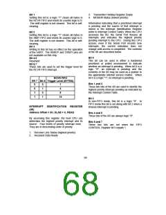
Bit 6,7
These bits are used to set the trigger level for
the RCVR FIFO interrupt.
RCVR FIFO
Bit 7
0
Bit 6 Trigger Level (BYTES)
Bits 1 and 2
0
1
0
1
1
These two bits of the IIR are used to identify the
highest priority interrupt pending as indicated by
the Interrupt Control Table.
0
1
1
4
8
14
Bit 3
In non-FIFO mode, this bit is a logic "0". In
FIFO mode this bit is set along with bit 2 when a
timeout interrupt is pending.
INTERRUPT IDENTIFICATION REGISTER
(IIR)
Address Offset = 2H, DLAB = X, READ
Bits 4 and 5
These bits of the IIR are always logic "0".
By accessing this register, the host CPU can
determine the highest priority interrupt and its
source. Four levels of priority interrupt exist.
They are in descending order of priority:
Bits 6 and 7
These two bits are set when the FIFO
CONTROL Register bit 0 equals 1.
1. Receiver Line Status (highest priority)
2. Received Data Ready
68

 SMSC [ SMSC CORPORATION ]