from the end of the execution phase of one of
the read/write commands to the head unload
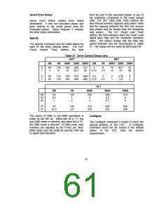
state. The SRT (Step Rate Time) defines the
time interval between adjacent step pulses. Note
that the spacing between the first and second
step pulses may be shorter than the remaining
Sense Drive Status
Sense Drive Status obtains drive status
information. It has not execution phase and
goes directly to the result phase from the
command phase. Status Register 3 contains
the drive status information.
step pulses.
The HLT (Head Load Time)
defines the time between when the Head Load
signal goes high and the read/write operation
starts. The values change with the data rate
speed selection and are documented in Table
27. The values are the same for MFM and FM.
Specify
The Specify command sets the initial values for
each of the three internal times. The HUT
(Head Unload Time) defines the time
Table 27 - Drive Control Delays (ms)
HUT
SRT
2M
1M
500K 300K 250K
2M
1M
500K 300K 250K
0
1
..
E
F
64
4
..
56
60
128
8
..
112
120
256
16
..
224
240
426
26.7
..
373
400
512
32
..
448
480
4
3.75
..
0.5
0.25
8
7.5
..
1
0.5
16
15
..
2
1
26.7
25
..
3.33
1.67
32
30
..
4
2
HLT
2M
1M
500K
300K
250K
00
01
02
..
64
0.5
1
128
1
2
256
2
4
426
3.3
6.7
..
512
4
8
..
..
..
.
7F
7F
63
63.5
126
127
252
254
420
423
504
508
The choice of DMA or non-DMA operations is
made by the ND bit. When this bit is "1", the
non-DMA mode is selected, and when ND is "0",
the DMA mode is selected. In DMA mode, data
transfers are signaled by the FDRQ pin. Non-
DMA mode uses the RQM bit and the FINT pin
to signal data transfers.
Configure
The Configure command is issued to select the
special features of the FDC. A Configure
command need not be issued if the default
values of the FDC meet the system
requirements.
61

 SMSC [ SMSC CORPORATION ]