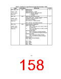
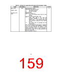
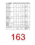
Table 73 - Auxiliary I/O, Logical Device 8 [Logical Device Number = 0x08]
NAME
REG INDEX
DEFINITION
Watch-dog timer Control
Bit[0] Watch-dog Status Bit, R/W
STATE
WDT_CTRL
0xF4
C
Default = 0x00
=1
=0
WD timeout occurred
WD timer counting
Bit[1] Reserved
Bit[2] Force Timeout, W
Cleared by VTR
POR
=1
Forces WD timeout event; this bit is self-
clearing
Bit[3] P20 Force Timeout Enable, R/W
= 1
Allows rising edge of P20, from the
Keyboard Controller, to force the WD
timeout event. A WD timeout event may
still be forced by setting the Force Timeout
Bit, bit 2.
= 0
P20 activity does not generate the WD
timeout event.
Note: The P20 signal will remain high for a minimum
of 1us and can remain high indefinitely. Therefore,
when P20 forced timeouts are enabled, a self-
clearing edge-detect circuit is used to generate a
signal which is ORed with the signal generated by
the Force Timeout Bit.
Bit[7:4] Reserved. Set to 0
159

 SMSC [ SMSC CORPORATION ]