SMBus Fan Control with 1°C Accurate Temperature Monitoring
Datasheet
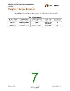
Chapter 2 Pin Layout
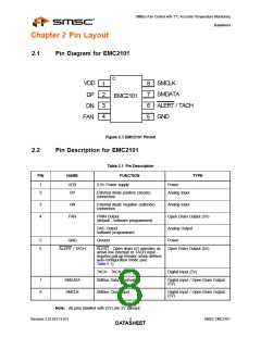
2.1
Pin Diagram for EMC2101
VDD
DP
SMCLK
8
7
6
5
1
2
3
4
SMDATA
ALERT / TACH
GND
EMC2101
DN
FAN
Figure 2.1 EMC2101 Pinout
2.2
Pin Description for EMC2101
Table 2.1 Pin Description
FUNCTION
3.3V Power supply
PIN
NAME
TYPE
1
2
VDD
DP
Power
External diode positive (anode)
connection
Analog Input
3
4
DN
External diode negative (cathode)
connection
Analog Input
FAN
PWM Output
(default - software programmed)
Open Drain Output (5V)
Analog Output
DAC Output
software programmed
5
6
GND
Ground
Power
ALERT / TACH
ALERT - Open drain I/O operates as
active low interrupt or TACH input -
requires pull-up resistor, which defines
auto-configuration mode (see
Table 5.1)
Open Drain Output (5V)
TACH - TACH input
Digital Input (5V)
7
8
SMDATA
SMCLK
SMBus Data input/output
Digital Input / Open-Drain Output
(5V)
SMBus Clock input
Digital Input / Open-Drain Output
(5V)
Note: All pins labelled with (5V) are 5V tolerant.
Revision 2.53 (03-13-07)
8
SMSC EMC2101
DATASHEET

 SMSC [ SMSC CORPORATION ]