5Mbps ARCNET (ANSI 878.1) Controller with 2K x 8 On-Chip RAM
Datasheet
6.4.3 Receive Sequence
A receive sequence begins with the RI status bit becoming a logic "1", which indicates that a previous
reception has concluded. The microcontroller will be interrupted if the corresponding bit in the Interrupt
Mask Register is set to logic "1". Otherwise, the microcontroller must periodically check the Status
Register. Once the microcontroller is alerted to the fact that the previous reception has concluded, it may
issue the "Enable Receive to Page fnn" command, which resets the RI bit to logic "0" and selects a new
page in the RAM buffer. Again, the appropriate buffer size is specified in the "Define Configuration"
command. Typically, the page which just received the data packet will be read by the microcontroller at
this point. Once the "Enable Receive to Page fnn" command is issued, the microcontroller attends to other
duties. There is no way of knowing how long the new reception will take, since another node may transmit
a packet at any time. When another node does transmit a packet to this node, and if the "Define
Configuration" command has enabled the reception of long packets, the COM20020ID interprets the
packet as either a long or short packet, depending on whether the content of the buffer location 2 is zero or
non-zero. The format of the buffer is shown in Figure 6.3. Address 0 contains the Source Identifier (SID),
Address 1 contains the Destination Identifier (DID), and Address 2 contains, for short packets, the value
256-N, where N represents the message length, or for long packets, the value 0, indicating that it is indeed
a long packet. In the latter case, Address 3 contains the value 512-N, where N represents the message
length. Note that on reception, the COM20020ID deposits packets into the RAM buffer in the same format
that the transmitting node arranges them, which allows for a message to be received and then
retransmitted without rearranging any bytes in the RAM buffer other than the SID and DID. Once the
packet is received and stored correctly in the selected buffer, the COM20020ID sets the RI bit to logic "1"
to signal the microcontroller that the reception is complete.
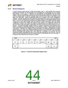
MSB
TRI
LSB
RI
TA
POR
TEST
RECON
TMA
TMA
TTA
TRI
TTA
Figure 6.3 – Command Chaining Status Register Queue
Revision 12-05-06
Page 44
SMSC COM20020I Rev D
DATASHEET

 SMSC [ SMSC CORPORATION ]