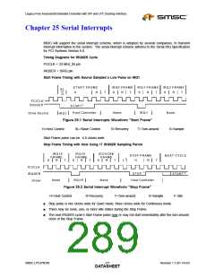
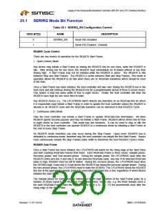
Legacy-Free Keyboard/Embedded Controller with SPI and LPC Docking Interface
Chapter 26 XNOR Chain Test Mode
An XNOR-Chain test structure is in to the LPC47N350 to allow users to confirm that all pins are in
contact with the motherboard during assembly and test operations (Figure 26.1).
The XNOR-Chain test structure must be activated to perform these tests. When the XNOR-Chain is
activated, the LPC47N350 pin functions are disconnected from the device pins, which all become input
pins except for one output pin at the end of XNOR-Chain.
The tests that are performed when the XNOR-Chain test structure is activated require the board-level
test hardware to control the device pins and observe the results at the XNOR-Chain output pin.
26.1
Pins in XNOR Chain Structure
All pins are inputs into the XNOR-Chain with the exception of the following pin:
■
■
■
■
■
■
■
■
■
■
VCC0 pins
VCC1 pins
VCC2 pins
AGND pin
VSS pin
XTAL1 pin
XTAL2 pin
XOSEL pin
nRESET_OUT pin (this is the XNOR-Chain output)
TEST_PIN (this is the XNOR-Chain enable input)
26.2
Entering and Exiting the XNOR Chain
The XNOR-Chain test is entered as follows in the LPC47N350:
■
Apply first rising edge on TEST_PIN. In this mode, KDAT, KCLK, IMDAT, and IMCLK are turned into
inputs.
■
Set KDAT = KCLK = IMDAT = 0 and IMCLK = 1. Apply another rising edge of TEST_PIN, the part
enters the XNOR-Chain test mode.
When activated, the test mode allows one single input pin, when switched, to toggle the nRESET_OUT
output.
The XNOR-Chain is exited as follows in the LPC47N350:
■
Set KDAT = KCLK = IMDAT = 0 and IMCLK = 0. Apply another rising edge of TEST_PIN, the part
exits the XNOR-Chain test mode.
SMSC LPC47N350
275
Revision 1.1 (01-14-03)
DATASHEET

 SMSC [ SMSC CORPORATION ]