Legacy-Free Keyboard/Embedded Controller with SPI and LPC Docking Interface
Chapter 25 Serial Interrupts
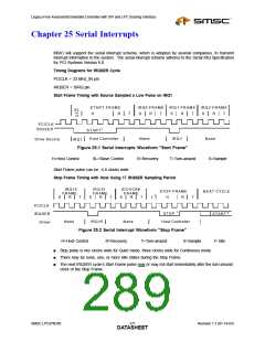
MSIO will support the serial interrupt scheme, which is adopted by several companies, to transmit
interrupt information to the system. The serial interrupt scheme adheres to the Serial IRQ Specification
for PCI Systems Version 6.0.
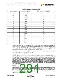
Timing Diagrams for IRQSER Cycle
PCICLK = 33 MHz_IN pin
IRQSER = SIRQ pin
Start Frame Timing with Source Sampled a Low Pulse on IRQ1
STAR T FR AM E
IR Q 0 FRAM E
IR Q 1 FR AM E
IR Q 2 FR AM E
SL
or
H
R
T
S
R
T
S
R
T
S
R
T
H
PCIC LK
IR Q SER
STAR T 1
H ost C ontroller
None
IR Q 1
N one
Drive Source
IR Q 1
Figure 25.1 Serial Interrupts Waveform "Start Frame"
H=Host Control SL=Slave Control R=Recovery T=Turn-around
S=Sample
Start Frame pulse can be 4-8 clocks wide.
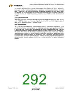
Stop Frame Timing with Host Using 17 IRQSER Sampling Period
IR Q 14
FR AM E
R
IR Q 15
FR AM E
R
IO C H C K#
FR A M E
STO P FR AM E
N EX T C YCLE
2
S
T
S
T
S
R
T
H
R
T
I
PC IC LK
IR Q SE R
D river
1
3
STO P
STAR T
N one
IR Q 15
N one
H ost C ontroller
Figure 25.2 Serial Interrupt Waveform "Stop Frame"
H=Host Control R=Recovery T=Turn-around S=Sample
I= Idle
■
■
■
Stop pulse is two clocks wide for Quiet mode, three clocks wide for Continuous mode.
There may be none, one, or more Idle states during the Stop Frame.
The next IRQSER cycle’s Start Frame pulse may or may not start immediately after the turn-around
clock of the Stop Frame.
SMSC LPC47N350
271
Revision 1.1 (01-14-03)
DATASHEET

 SMSC [ SMSC CORPORATION ]