ST7781
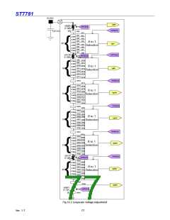
Ladder Resistors and 8-to-1 Selector Block Configuration
The reference voltage generation block consists of two ladder resistor units including variable resistors and 8-to-1 selectors.
Each 8-10-1 selector selects one of the 8 voltage levels generated from the ladder resistor unit to output as a grayscale
reference voltage. Both variable resistors and 8-to-1 selectors are controlled according to theγ-correction registers. This
unit has pins to connect a volume resistor externally to compensate differences in various characteristic of panels.
Variable Resistors
ST7781 uses variable resistors of the following three purposes: gradient adjustment (VRCP(N)0/VRCP(N)1);amplitude
adjustment (1) (VROP(N)0); and the amplitude adjustment (2) (VROP(N)1). The resistance values of these variable
resistors are set by gradient adjustment registers and amplitude adjustment registers as follows.
Gradient Adjustment
PRP(N)0/1[2:0] VRCP(N)0
Amplitude Adjustment (1)
Amplitude Adjustment (2)
VRP(N)0[3:0]
VROP(N)0
VRP(N)1[4:0]
Register
00000
00001
00010
:
VROP(N)1
Resistance
Register
Resistance
Register
0000
0001
0010
:
Resistance
000
0R
0R
2R
4R
:
0R
1R
2R
:
001
4R
010
8R
011
12R
100
16R
:
:
:
:
101
110
111
20R
24R
28R
1101
1111
1111
26R
28R
30R
11101
11110
11111
29R
30R
31R
Table 16.5: Resistance Adjustment
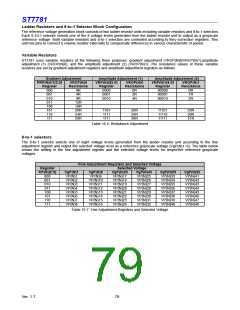
8-to-1 selectors
The 8-to-1 selector selects one of eight voltage levels generated from the ladder resistor unit according to the fine
adjustment register and output the selected voltage level as a reference grayscale voltage (VgP(N)1~6). The table below
shows the setting in the fine adjustment register and the selected voltage levels for respective reference grayscale
voltages.
Fine Adjustment Registers and Selected Voltage
Register
KP(N)[2:0]
000
Selected Voltage
VgP(N)1
VP(N)1
VP(N)2
VP(N)3
VP(N)4
VP(N)5
VP(N)6
VP(N)7
VP(N)8
VgP(N)8
VP(N)9
VgP(N)20
VgP(N)43
VP(N)25
VP(N)26
VP(N)27
VP(N)28
VP(N)29
VP(N)30
VP(N)31
VP(N)32
VgP(N)55
VP(N)33
VP(N)34
VP(N)35
VP(N)36
VP(N)37
VP(N)38
VP(N)39
VP(N)40
VgP(N)62
VP(N)41
VP(N)42
VP(N)43
VP(N)44
VP(N)45
VP(N)46
VP(N)47
VP(N)48
VP(N)17
VP(N)18
VP(N)19
VP(N)20
VP(N)21
VP(N)22
VP(N)23
VP(N)24
001
010
011
100
101
110
111
VP(N)10
VP(N)11
VP(N)12
VP(N)13
VP(N)14
VP(N)15
VP(N)16
Table 16.7: Fine Adjustment Registers and Selected Voltage
Ver. 1.7
79

 SITRONIX [ SITRONIX TECHNOLOGY CO., LTD. ]