EFR32MG13 Mighty Gecko Multi-Protocol Wireless SoC Family Data Sheet
Electrical Specifications
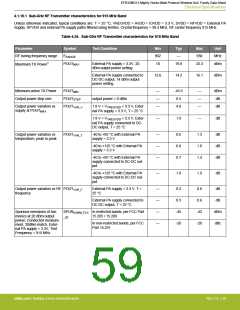
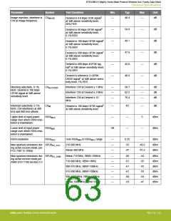
4.1.10.1 Sub-GHz RF Transmitter characteristics for 915 MHz Band
Unless otherwise indicated, typical conditions are: T = 25 °C, VREGVDD = AVDD = IOVDD = 3.3 V, DVDD = RFVDD = External PA
Supply. RFVDD and external PA supply paths filtered using ferrites. Crystal frequency = 38.4 MHz. RF center frequency 915 MHz.
Table 4.24. Sub-GHz RF Transmitter characteristics for 915 MHz Band
Parameter
Symbol
FRANGE
Test Condition
Min
902
18
Typ
—
Max
930
Unit
MHz
dBm
RF tuning frequency range
Maximum TX Power1
POUTMAX
External PA supply = 3.3V, 20
dBm output power setting
19.8
23.3
External PA supply connected to
DC-DC output, 14 dBm output
power setting
12.6
14.2
16.1
dBm
Minimum active TX Power
Output power step size
POUTMIN
—
—
—
-45.5
0.5
—
—
—
dBm
dB
POUTSTEP
POUTVAR_V
output power > 0 dBm
Output power variation vs
supply at POUTMAX
1.8 V < VVREGVDD < 3.3 V, Exter-
nal PA supply = 3.3 V, T = 25 °C
4.8
dB
1.8 V < VVREGVDD < 3.3 V, Exter-
nal PA supply connected to DC-
DC output, T = 25 °C
—
1.9
—
dB
Output power variation vs
temperature, peak to peak
POUTVAR_T
-40 to +85 °C with External PA
supply = 3.3 V
—
—
—
0.6
0.8
0.7
1.3
1.6
1.4
dB
dB
dB
-40 to +125 °C with External PA
supply = 3.3 V
-40 to +85 °C with External PA
supply connected to DC-DC out-
put
-40 to +125 °C with External PA
supply connected to DC-DC out-
put
—
1.0
1.9
dB
Output power variation vs RF POUTVAR_F
frequency
External PA supply = 3.3 V, T =
25 °C
—
—
—
—
0.2
0.3
-45
-26
0.6
0.6
-42
-20
dB
dB
External PA supply connected to
DC-DC output, T = 25 °C
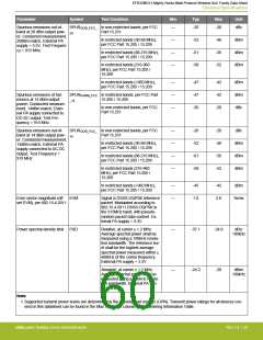
Spurious emissions of har-
monics at 20 dBm output
power, Conducted measure-
ment, 20dBm match, Exter-
nal PA supply = 3.3V, Test
Frequency = 915 MHz
SPURHARM_FCC In restricted bands, per FCC Part
dBm
dBc
15.205 / 15.209
_20
In non-restricted bands, per FCC
Part 15.231
silabs.com | Building a more connected world.
Rev. 1.4 | 59

 SILICON [ SILICON ]