EFM32G Data Sheet
Electrical Characteristics
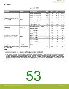
4.9.4 HFRCO
Parameter
Table 4.11. HFRCO
Symbol
Test Condition
Min
Typ
28
Max
Unit
MHz
MHz
MHz
MHz
MHz
28 MHz frequency band
21 MHz frequency band
14 MHz frequency band
11 MHz frequency band
7 MHz frequency band
27.16
20.37
13.58
10.67
6.402
28.84
21.63
14.42
11.33
6.798
21
14
Oscillation frequency, VDD= 3.0
V, TAMB=25 ºC
fHFRCO
11
6.61
1.22
0.6
25
1 MHz frequency band
1.164
1.236
MHz
After start-up, fHFRCO = 14 MHz
After band switch
—
—
—
—
Cycles
Cycles
µA
tHFRCO_settling
Settling time
fHFRCO = 28 MHz
fHFRCO = 21 MHz
fHFRCO = 14 MHz
fHFRCO = 11 MHz
fHFRCO = 6.6 MHz
fHFRCO = 1.2 MHz
fHFRCO = 14 MHz
—
158
125
99
190
155
120
110
90
—
µA
—
µA
Current consumption (Produc-
tion test condition = 14 MHz)
IHFRCO
—
88
µA
—
72
µA
—
24
32
µA
Duty cycle
DCHFRCO
48.5
—
50
51
%
0.33
Frequency step for LSB change TUNESTEPHFRCO
in TUNING value
—
%
Note:
1. For devices with prod. rev. < 19, Typ = 7 MHz and Min/Max values not applicable.
2. For devices with prod. rev. < 19, Typ = 1 MHz and Min/Max values not applicable.
3. The TUNING field in the CMU_HFRCOCTRL register may be used to adjust the HFRCO frequency. There is enough adjustment
range to ensure that the frequency bands above 7 MHz will always have some overlap across supply voltage and temperature.
By using a stable frequency reference such as the LFXO or HFXO, a firmware calibration routine can vary the TUNING bits and
the frequency band to maintain the HFRCO frequency at any arbitrary value between 7 MHz and 28 MHz across operating condi-
tions.
silabs.com | Building a more connected world.
Rev. 2.10 | 53

 SILICON [ SILICON ]