C8051F52x-53x
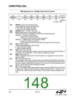
SFR Definition 16.1. SCON0: Serial Port 0 Control
R/W
R
R/W
R/W
R/W
R/W
R/W
R/W
Reset Value
S0MODE
-
MCE0
REN0
TB80
RB80
TI0
RI0
01000000
Bit
Bit7
Bit6
Bit5
Bit4
Bit3
Bit2
Bit1
Bit0
Addressable
SFR Address:
0x98
Bit7:
S0MODE: Serial Port 0 Operation Mode.
This bit selects the UART0 Operation Mode.
0: 8-bit UART with Variable Baud Rate.
1: 9-bit UART with Variable Baud Rate.
UNUSED. Read = 1b. Write = don’t care.
MCE0: Multiprocessor Communication Enable.
Bit6:
Bit5:
The function of this bit is dependent on the Serial Port 0 Operation Mode.
S0MODE = 0: Checks for valid stop bit.
0: Logic level of stop bit is ignored.
1: RI0 will only be activated if stop bit is logic level 1.
S0MODE = 1: Multiprocessor Communications Enable.
0: Logic level of ninth bit is ignored.
1: RI0 is set and an interrupt is generated only when the ninth bit is logic 1.
REN0: Receive Enable.
Bit4:
This bit enables/disables the UART receiver.
0: UART0 reception disabled.
1: UART0 reception enabled.
Bit3:
Bit2:
Bit1:
TB80: Ninth Transmission Bit.
The logic level of this bit will be assigned to the ninth transmission bit in 9-bit UART Mode. It
is not used in 8-bit UART Mode. Set or cleared by software as required.
RB80: Ninth Receive Bit.
RB80 is assigned the value of the STOP bit in Mode 0; it is assigned the value of the 9th
data bit in Mode 1.
TI0: Transmit Interrupt Flag.
Set by hardware when a byte of data has been transmitted by UART0 (after the 8th bit in 8-
bit UART Mode, or at the beginning of the STOP bit in 9-bit UART Mode). When the UART0
interrupt is enabled, setting this bit causes the CPU to vector to the UART0 interrupt service
routine. This bit must be cleared manually by software.
RI0: Receive Interrupt Flag.
Bit0:
Set to ‘1’ by hardware when a byte of data has been received by UART0 (set at the STOP bit
sampling time). When the UART0 interrupt is enabled, setting this bit to ‘1’ causes the CPU
to vector to the UART0 interrupt service routine. This bit must be cleared manually by soft-
ware.
148
Rev. 0.3

 SILICON [ SILICON ]