BATTERY PROTECTION IC FOR 1-CELL PACK
S-8211C Series
Rev.5.0_00
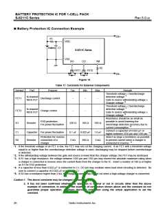
Battery Protection IC Connection Example
EB+
R1
VDD
Battery C1
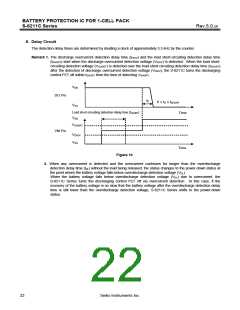
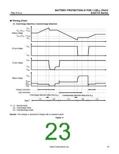
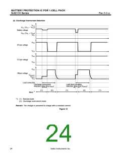
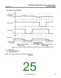
S-8211C Series
VSS
DO
CO
VM
R2
FET1
FET2
EB−
Figure 14
Table 17 Constants for External Components
Symbol
FET1
Part
Purpose
Typ.
Min.
Max.
Remark
Threshold voltage ≤ Overdischarge
N-channel
MOS FET
detection voltage *1
Discharge control
−
−
−
Gate to source withstanding voltage ≥
Charger voltage *2
Threshold voltage ≤ Overdischarge
N-channel
MOS FET
detection voltage *1
FET2
R1
Charge control
−
−
−
Gate to source withstanding voltage ≥
Charger voltage *2
Resistance should be as small as
possible to avoid lowering the
overcharge detection accuracy due to
current consumption. *3
ESD protection,
For power fluctuation
Resistor
220 Ω
100 Ω
330 Ω
Connect a capacitor of 0.022 µF or
higher between VDD pin and VSS pin. *4
Select as large a resistance as possible
to prevent current when a charger is
connected in reverse. *5
C1
R2
Capacitor For power fluctuation
Protection for reverse
0.1 µF
2 kΩ
0.022 µF
300 Ω
1.0 µF
2 kΩ
Resistor
connection of a
charger
*1. If the threshold voltage of an FET is low, the FET may not cut the charging current. If an FET with a threshold voltage
equal to or higher than the overdischarge detection voltage is used, discharging may be stopped before overdischarge
is detected.
*2. If the withstanding voltage between the gate and source is lower than the charger voltage, the FET may be destroyed.
*3. If R1 has a high resistance, the voltage between VDD pin and VSS pin may exceed the absolute maximum rating when
a charger is connected in reverse since the current flows from the charger to the IC. Insert a resistor of 100 Ω or higher
as R1 for ESD protection.
*4. If a capacitor of less than 0.022 µF is connected to C1, DO pin may oscillate when load short-circuiting is detected. Be
sure to connect a capacitor of 0.022 µF or higher to C1.
*5. If R2 has a resistance higher than 2 kΩ, the charging current may not be cut when a high-voltage charger is connected.
Caution 1. The above constants may be changed without notice.
2. It has not been confirmed whether the operation is normal or not in circuits other than the above
example of connection. In addition, the example of connection shown above and the constant do not
guarantee proper operation. Perform thorough evaluation using the actual application to set the
constant.
26
Seiko Instruments Inc.

 SII [ SEIKO INSTRUMENTS INC ]