PC929
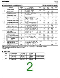
■
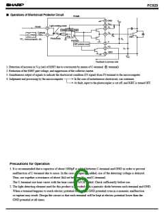
Operations of Shortcircuit Protector Circuit
PC929
14 GND
V
CC
V
CC
13
12
Light emitting diode
Anode
O
1
3
Constant voltage circuit
Cathode
O
2
11
1
R
Amp.
G
IGBT
Photodiode
R
TTL, microcomputer, etc.
C
Interface
C
9
8
IGBT protector circuit
FS
C
P
GND
10
V
EE
Feedback to primary side
1. Detection of increase in VCE (sat) of IGBT due to overcurrent by means of C-terminal
2. Reduction of the IGBT gate voltage, and suppression of the collector current.
9 terminal)
3. Simultaneous output of signals to indicate the shortcircuit condition (FS signal) from FS terminal to the microcomputer
4. Judgement and processing by the microcomputer
In the case of instantaneous shortcircuit, run continues.
At fault, input to the photocoupler is cut off, and IGBT is turned OFF.
Precautions for Operation
1. It is recommended that a capacitor of about 1000pF is added between C-terminal and GND in order to prevent
malfunction of C-terminal due to noise. In the case of capacitor added, rise of the detecting voltage is delayed.
Thus, use together a resistance of about 1kΩ set between V and C-terminal.
cc
The C-terminal rise time varies with the time constant of CR added. Check sufficiently before use.
2. The light-detecting element used for this product is provided with a parasitic diode between each terminal and GND.
When a terminal happens to reach electric potential lower than GND potential even in a moment, malfunction
or rupture may result. Design the circuit so that each terminal will be kept at electric potential lower than the
GND potential at all times.

 SHARP [ SHARP ELECTRIONIC COMPONENTS ]