SX1231
ADVANCED COMMUNICATIONS & SENSING
DATASHEET
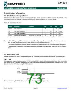
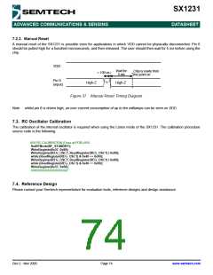
7.2.2. Manual Reset
A manual reset of the SX1231 is possible even for applications in which VDD cannot be physically disconnected. Pin 6
should be pulled high for a hundred microseconds, and then released. The user should then wait for 5 ms before using the
chip.
VDD
Wait for
5 ms
Chip is ready from
this point on
> 100 us
’’1’’
Pin 6
(input)
High-Z
High-Z
Figure 37. Manual Reset Timing Diagram
Note whilst pin 6 is driven high, an over current consumption of up to ten milliamps can be seen on VDD.
7.3. RC Oscillator Calibration
The calibration of the internal oscillator is required when using the Listen mode of the SX1231. The calibration procedure
source code is the following:
/////// RC CALIBRATION (Once at POR) ///////
SetRFMode(RF_STANDBY);
WriteRegister(0x57, 0x80);
WriteRegister(REG_OSC1, ReadRegister(REG_OSC1) | 0x80);
while (ReadRegister(REG_OSC1) & 0x40 == 0x00);
WriteRegister(REG_OSC1, ReadRegister(REG_OSC1) | 0x80);
while (ReadRegister(REG_OSC1) & 0x40 == 0x00);
WriteRegister(0x57, 0x00);
////////////////////////////////////////////
7.4. Reference Design
Please contact your Semtech representative for evaluation tools, reference designs and design assistance.
Rev 2 - Nov 2009
Page 74
www.semtech.com

 SEMTECH [ SEMTECH CORPORATION ]