SX1232
WIRELESS & SENSING
DATASHEET
4. Operating Modes
4.1. General Overview
The SX1232 has several working modes, manually programmed in RegOpMode. Fully automated mode selection, packet
transmission and reception is also possible using the Top Level Sequencer described in Section 4.5.
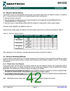
Table 20 Basic Transceiver Modes
Mode
000
001
010
011
Selected mode
Sleep mode
Standby mode
Symbol
Sleep
Enabled blocks
None
Stdby
Top regulator and crystal oscillator
Frequency synthesiser to Tx frequency FSTx
Transmit mode Tx
Frequency synthesiser to Rx frequency FSRx
Receive mode Rx
Frequency synthesizer at Tx frequency (Frf)
Frequency synthesizer and transmitter
Frequency synthesizer at frequency for reception (Frf-IF)
Frequency synthesizer and receiver
100
101
When switching from a mode to another, the sub-blocks are woken up according to a pre-defined and optimized sequence.
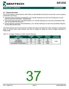
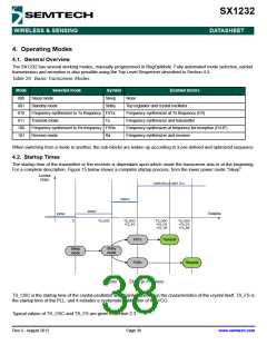
4.2. Startup Times
The startup time of the transmitter or the receiver is dependant upon which mode the transceiver was in at the beginning.
For a complete description, Figure 15 below shows a complete startup process, from the lower power mode “Sleep”.
Current
Drain
IDDR (Rx) or IDDT (Tx)
IDDFS
IDDST
IDDSL
Timeline
0
TS_OSC
TS_OSC
+TS_FS
TS_OSC
+TS_FS
+TS_TR
TS_OSC
+TS_FS
+TS_RE
FSTx
Transmit
Stdby
mode
Sleep
mode
FSRx
Receive
Figure 15. Startup Process
TS_OSC is the startup time of the crystal oscillator, and mainly depends on the characteristics of the crystal itself. TS_FS is
the startup time of the PLL, and it includes a systematic calibration of the VCO.
Typical values of TS_OSC and TS_FS are given in section 2.3.
Rev 3 - August 2012
Page 38
www.semtech.com

 SEMTECH [ SEMTECH CORPORATION ]