SX1232
WIRELESS & SENSING
DATASHEET
3.5.7. Bit Synchronizer
The Bit Synchronizer is a block that provides a clean and synchronized digital output, free of glitches. Its output is made
available on pin DIO1/DCLK in Continuous mode and can be disabled through register settings. However, for optimum
receiver performance its use when running Continuous mode is strongly advised.
The Bit Synchronizer is automatically activated in Packet mode. Its bit rate is controlled by BitRateMsb and BitRateLsb in
RegBitrate.
Raw demodulator
output
(FSK or OOK)
DATA
BitSync Output
To pin DATA and
DCLK in continuous
mode
DCLK
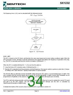
Figure 12. Bit Synchronizer Description
To ensure correct operation of the Bit Synchronizer, the following conditions have to be satisfied:
A preamble (0x55 or 0xAA) of at least 12 bits is required for synchronization, the longer the synchronization the better
the packet success rate
The subsequent payload bit stream must have at least one transition form '0' to '1' or '1' to '0 every 16 bits during data
transmission
The bit rate matching between the transmitter and the receiver must be better than 6.5%.
3.5.8. Frequency Error Indicator
This function provides information about the frequency error of the local oscillator (LO) compared with the carrier frequency
of a modulated signal at the input of the receiver. When the FEI block is launched, the frequency error is measured and the
signed result is loaded in FeiValue in RegFei, in 2’s complement format. The time required for an FEI evaluation is 4 times
the bit period.
To ensure a proper behavior of the FEI:
The operation must be done during the reception of preamble
The sum of the frequency offset and the 20 dB signal bandwidth must be lower than the base band filter bandwidth
The 20 dB bandwidth of the signal can be evaluated as follows (double-side bandwidth):
BR
2
⎛
⎞
⎠
-------
+
BW20dB = 2 × FDEV
⎝
Rev 3 - August 2012
Page 33
www.semtech.com

 SEMTECH [ SEMTECH CORPORATION ]