SX1232
WIRELESS & SENSING
DATASHEET
Towards
-125 dBm
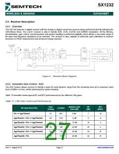
AgcStep2
AgcStep3
AgcStep4
AgcStep5
AgcStep1
Pin [dBm]
G1
G2
G3
G4
G5
G6
Higher Sensitivity
Lower Linearity
Lower Sensitivity
Higher Linearity
Lower Noise Figure
Higher Noise Figure
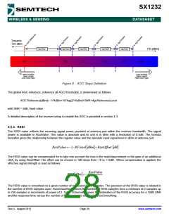
Figure 9. AGC Steps Definition
The global AGC reference, reference all AGC thresholds, is determined as follows:
AGC Reference[dBm]=-174dBm+10*log(2*RxBw)+SNR+AgcReferenceLevel
with SNR = 8dB, fixed value
A detailed description of the receiver setup to enable the AGC is provided in section 4.3.
3.5.3. RSSI
The RSSI value reflects the incoming signal power provided at antenna port within the receiver bandwidth. The signal
power is available in RssiValue. This value is absolute and its unit is in dBm with a resolution of 0.5dB. The formula
hereafter gives the relationship between the register value and the absolute input signal level in dBm at antenna port:
RssiValue = −2⋅ RF level
dBm
]
+ RssiOffset
dB
]
The RSSI value can be compensated for to take into account the loss in the matching network or the gain of an additional
LNA, by using RssiOffset. The offset can be chosen in 1dB steps from -16 to +15dB. When compensation is applied, the
effective signal strength is read as follows:
RssiValue
RSSI
[
dBm = −
]
2
The RSSI value is smoothed on a given number of measured RSSI samples. The precision of the RSSI value is related to
the number of RSSI samples used. RssiSmoothing selects the number of RSSI samples from a minimum of 2 samples up
to 256 samples in increments of power of 2. Table 16 hereafter gives the estimation of the RSSI accuracy for a 10dB SNR
and the response time versus the number of RSSI samples selected in RssiSmoothing.
Rev 3 - August 2012
Page 28
www.semtech.com

 SEMTECH [ SEMTECH CORPORATION ]