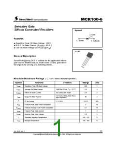
MCR100-6
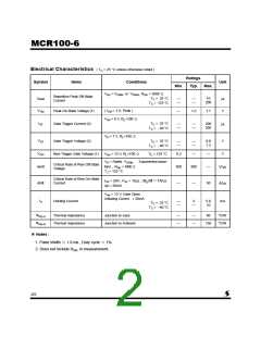
Electrical Characteristics ( TC = 25 °C unless otherwise noted )
Ratings
Typ.
Symbol
Items
Conditions
Unit
Min.
Max.
V
AK = VDRM or VRRM ; RGK = 1000 Ω
Repetitive Peak Off-State
Current
IDRM
VTM
IGT
TC = 25 °C
10
200
─
─
─
─
㎂
TC = 125 °C
( ITM = 1 A, Peak )
Peak On-State Voltage (1)
Gate Trigger Current (2)
1.2
1.7
V
─
VAK = 6 V, RL=100 Ω
TC = 25 °C
200
500
─
─
─
─
㎂
TC = - 40 °C
VD = 7 V, RL=100 Ω
VGT
VGD
dv/dt
TC = 25 °C
Gate Trigger Voltage (2)
0.8
1.2
V
V
─
─
─
─
TC = - 40 °C
V
AK = 12 V, RL=100 Ω
TC = 125 °C
Non-Trigger Gate Voltage (1)
0.2
─
─
─
V
D = Rated VDRM , Exponential wave-
Critical Rate of Rise Off-State
Voltage
form , RGK = 1000 Ω
500
800
V/㎲
TJ = 125 °C
Critical Rate of Rise On-State
Current
I
PK = 20A ; PW = 10㎲ ; diG/dt = 1A/㎲
di/dt
50
A/㎲
─
─
Igt = 20mA
VAK = 12 V, Gate Open
Initiating Curent = 20mA
IH
Holding Current
2
─
5.0
10
mA
─
─
T
C = 25 °C
TC = - 40 °C
Rth(j-c)
Rth(j-a)
Thermal Impedance
Thermal Impedance
Junction to case
60
°C/W
°C/W
─
─
─
─
Junction to Ambient
150
※ Notes :
1. Pulse Width ≤ 1.0 ms , Duty cycle ≤ 1%
2. Does not include RGK in measurement.
2/5

 SEMIWELL [ SEMIWELL SEMICONDUCTOR ]