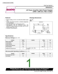
STK4151V
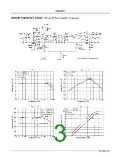
Operating Characteristics at Ta = 25°C, V = ±28.0V, R = 8Ω (non-inductive), Rg = 600Ω, VG = 40dB
CC
L
unless otherwise specified, at specified test circuit (based on sample application
circuit)
Parameter
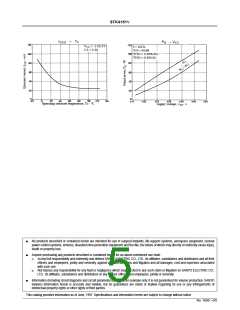
Quiescent current
Symbol
Conditions
33.5V
min
typ
40
max
Unit
I
V
=
±
20
100
mA
CCO
CC
f = 20Hz to 20kHz,
THD = 0.08%
P
(1)
(2)
30
35
W
W
O
O
Output power
V
= ±25V, f = 1kHz,
CC
P
THD = 0.2%, R = 4
Ω
L
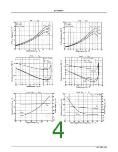
Total harmonic distortion
Frequency response
THD
f , f
f = 1kHz, Po = 1W
+0
0.08
%
Po = 1W,
dB
20 to 50k
55
Hz
L
H
−3
Input impedance
Output noise voltage
Neutral voltage
r
f = 1kHz, Po = 1W
kΩ
i
V
V
=
=
±
33.5V, Rg = 10k
Ω
1.2
mVrms
mV
NO
CC
CC
V
V
±33.5V
−70
0
+70
N
Muting voltage
V
−2
−5
−10
V
M
Note :
For power supply at the time of test, use a constant-voltage power supply
unless otherwise specified.
*
For measurement of the available time for load short-circuit and output
noise voltage, use the specified transformer power supply shown right.
** The output noise voltage is represented by the peak value on rms scale
(VTVM) of average value indicating type. For AC power supply, use an AC
stabilized power supply (50Hz) to eliminate the effect of flicker noise in AC
primary line.
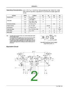
Specified transformer power supply
(Equivalent to RP-25)
Equivalent Circuit
No. 1650—2/5

 SANYO [ SANYO SEMICON DEVICE ]