LM8562
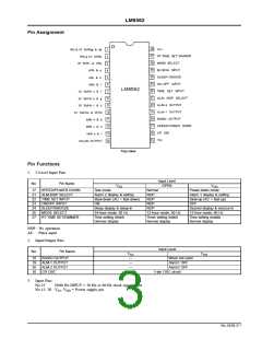
4. Output Pins
Drive Phase
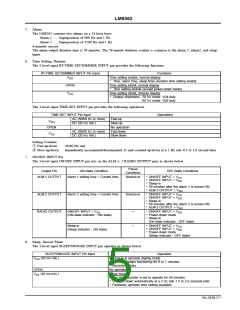
10’SHR eg
No.
Pin Name
1
2
1
2
AM & 10’SHR ag & de
PM & 10’SHR b
10’SHR c & HR e
HR b & g
AM 10’SHR ad
PM
10’SHR b
10’SHR c
HR b
3
HR e
4
HR g
5
HR c & d
HR d
HR c
6
HR a & f
HR f
HR a
7
10’SMIN a & f
10’SMIN b & g
10’SMIN c & d
10’SMIN e & MIN e
MIN b & g
10’SMIN a
10’SMIN b
10’SMIN c
MIN e
MIN g
MIN d
MIN f
10’SMIN f
10’SMIN g
10’SMIN d
10’SMIN e
MIN b
8
9
10
11
12
13
14
MIN c & d
MIN c
MIN a & f
MIN a
COLON OUTPUT
COLON
—
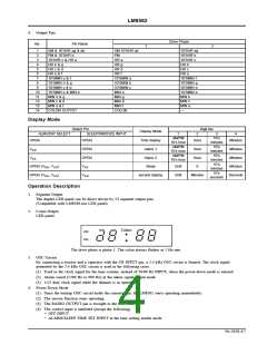
Display Mode
Select Pin
SLEEP/SNOOZE INPUT
Digit No.
Display Mode
Time display
Alarm 1
ALM-DISP SELECT
OPEN
1
2
3
4
AM/PM
10’s hour
10’s
minutes
OPEN
Hour
Minutes
AM/PM
10’s hour
10’s
minutes
V
OPEN
OPEN
Hour
Hour
0
Minutes
Minutes
Minutes
Seconds
DD
SS
AM/PM
10’s hour
10’s
minutes
V
Alarm 2
10’s
minutes
OPEN (V , V
DD SS
)
)
V
Sleep
Unlit
Unlit
SS
DD
10’s
seconds
OPEN (V , V
DD SS
V
second display
Minutes
Operation Description
1. Segment Output
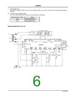
The duplex LED panel can be direct driven by 13 segment output pins.
(Compatible with LM8560-use LED panel)
2. Colon Output
LED panel
Colon
The drive phase is phase 1. The colon always flashes at 1 Hz rate.
3. OSC Circuit
By connecting a resistor and a capacitor with the CR INPUT pin, a 2.4 kHz OSC circuit is formed. The clock signal
generated by the 2.4 kHz OSC circuit is used in the following cases.
(1) Used as the clock signal for the time counter, instead of 50/60 Hz INPUT, when the power-down mode is entered.
(2) Alarm sound (1200 Hz or 600 Hz) at the alarm signal output mode
(3) 1/25 duty clock signal while the dimmer is in operation
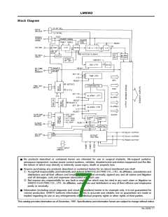
4. Power-Down Mode
(1) Since the backup OSC circuit holds the current time, the LM8562 starts operating immediately.
(2) The snooze function stops operating.
(3) The RADIO OUTPUT pin is brought to the OFF state.
(4) The control input is inhibited (except the following).
.
OFF INPUT
.
ALARM/SLEEP TIME SET INPUT at the time setting enable mode
No.2658-4/7

 SANYO [ SANYO SEMICON DEVICE ]