LC89057W-VF4A-E
13. Application Example
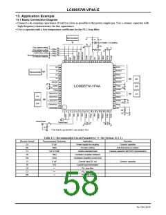
13.1 Basic Connection Diagram
•
Connect a de-coupling capacitance (0.1μF) as close as possible to the power supply pin. Use a ceramic capacitor with
high-frequency characteristics for this capacitance.
•
Use a capacitor with a low temperature coefficient for the PLL loop filter.
Microcontroller
Cl
Cl
24.576MHz / 12.288MHz
Cc
Rd
Cc
Rf
Chip address setting
Rp
Rp
Rp
Rp
Chip address setting
Demodulation function
master/slave setting
Modulation/general-purpose
I/O function selection
36 35 34 33 32 31 30 29 28 27 26 25
37
24
23
22
21
20
19
18
17
16
15
14
13
DO
DI
ADIN
38
39
40
41
42
43
44
45
46
47
48
SLRCK
SBCK
Microcontroller
CE
CL
RDATA
RLRCK
A/D
DSP
D/A
XMODE
DGND
DV
DD
LC89057W-VF4A
Cc
Cc
DGND
RBCK
RMCK
AGND
DV
DD
TMCK/PIO0
TBCK/PIO1
A/D
TLRCK/PIO2
TDATA/PIO3
TXO/PIOEN
Cc
DSP
AV
DD
LPF
R0
C0
1
2
3
4
5
6
7
8
9
10 11 12
C1
Coaxial Input
Ri
Optical Input
Cc
Cc
Ci
* For how to use the RX1, see section 10.2.
Table 13.1 Recommended Circuit Parameters (∗∗: See Section 10.1.1)
Element Symbol
Recommended Parameter
Application
Power supply de-coupling
Function setting
Remarks
Cc
Rp
C1
Rf
0.1μF
10kΩ
1pF to 33pF
1MΩ
Ceramic capacitor
Pull-down/pull-up resistor
Quarts resonator load
Oscillation amplifier feedback
Oscillation amplifier current limit
Coaxial input DC cut
Coaxial input termination
PLL loop filter
Ceramic capacitor with NP0 characteristics
Rd
Ci
220Ω
0.1μF
75Ω
Ceramic capacitor
Ri
C0
C1
R0
∗∗
∗∗
PLL loop filter
∗∗
PLL loop filter
No.7202-58/59

 SANYO [ SANYO SEMICON DEVICE ]