Mechanical test and Environmental Substance
Requirement
Test Conditions
No.
Item
SCK, SCG, SSC,
SSD Type
SCC Type
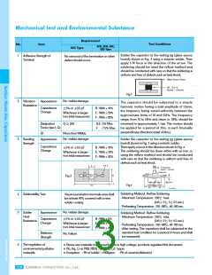
Solder the capacitor to the testing jig (glass epoxy
board) shown in Fig. 2 using a eutectic solder. Then
apply 5 N force in the direction of the arrow. The
soldering should be used the reflow method and
should be conducted with care so that the soldering is
uniform and free of defects such as heat shock.
1
Adhesive Strength of
Terminal
No removal of the termination or other
defect should occur.
Fig.2
2
No. visible damage
Vibration
Resistance
Appearance
The capacitor should be subjected to a simple
harmonic motion having a total amplitude of 1.5mm,
the frequency being varied uniformly between the
approximate limits of 10 and 55Hz. The frequency
range, from 10 to 55Hz and return to 10Hz, should be
traversed in approximately 1 min. This motion should
be applied for a period of 2hrs. in each 3mutually
perpendicular directions (total of 6hrs.)
Capacitance
Change
±5% or ±0.5 pF
B : With 10%
E : With 20%
F : With 30%
Whichever is larger
from initial measurement
Dissipation
Q ≥ 200
B,E : 5% Max.
Factor (tan
δ, Q)
F
: 7.5% Max.
I.R
More than 1000MΩ
3
No. visible damage
Bending
Strength
Appearance
Solder the capacitor to the testing jig (glass epoxy
board) shown in Fig. 3 using a eutectic solder.
Then apply a force in the direction shown in Fig. 4.
The soldering should be done either with an iron or
using the reflow method and should be conducted
with care so that the soldering is uniform and free of
defects such as heat shock.
Capacitance
Change
±5% or ±0.5 pF
B : With 10%
E : With 20%
F : With 30%
Whichever is larger
from initial measurement
Fig.3
Fig.4
Soldering Method : Reflow Soldering
- Maximum Temperature : 250℃ max.
(245± 5℃, 5± 0.5 sec.)
4
5
Solderability Test
Visual examination terminals area shall
be at least 90% covered with a new
solder coating
- Preheating Temperature : 150~180℃, 60~180 sec.
No. visible damage
Solder
Heat
Resistance
Appearance
Soldering Method : Reflow Soldering
- Maximum Temperature : 250℃ max.
(245± 5℃, 5± 0.5 sec.)
- Preheating Temperature : 150~180℃, 60~180 sec.
- After testing, The capacitors shall be subjected to the
standard test condition for a period 24 hours and shall
be measured.
Capacitance
Change
±5% or ±0.5 pF
B : With 5%
E : With 15%
F : With 20%
Whichever is larger
rom initial measurement
f
Dielectric
Strength
No. Failure
6
The regulation of
environmental pollution
materials.
※ Never use materials mentioned below in high voltage products regulated this document.
※ Pb, Hg, Cr+6, PBB, PBDE : 100ppm, Cd : 5ppm
※ Exception : - Pb of solder : <1000ppm - Pb of ceramic(dielectric)
138
SAMWHA CAPACITOR Co., Ltd.

 SAMWHA [ SAMWHA ELECTRIC ]