Rev. 1.01
K4B2G0446D
K4B2G0846D
datasheet
DDR3L SDRAM
10. IDD Current Measure Method
10.1 IDD Measurement Conditions
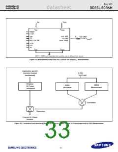
In this chapter, IDD and IDDQ measurement conditions such as test load and patterns are defined. Figure 19 shows the setup and test load for IDD and
IDDQ measurements.
- IDD currents (such as IDD0, IDD1, IDD2N, IDD2NT, IDD2P0, IDD2P1, IDD2Q, IDD3N, IDD3P, IDD4R, IDD4W, IDD5B, IDD6, IDD6ET, IDD6TC and
IDD7) are measured as time-averaged currents with all VDD balls of the DDR3 SDRAM under test tied together. Any IDDQ current is not included in
IDD currents.
- IDDQ currents (such as IDDQ2NT and IDDQ4R) are measured as time-averaged currents with all VDDQ balls of the DDR3 SDRAM under test tied
together. Any IDD current is not included in IDDQ currents.
Attention : IDDQ values cannot be directly used to calculate IO power of the DDR3 SDRAM. They can be used to support correlation of simulated IO
power to actual IO power as outlined in Figure 20. In DRAM module application, IDDQ cannot be measured separately since VDD and VDDQ
are using one merged-power layer in Module PCB.
For IDD and IDDQ measurements, the following definitions apply :
- "0" and "LOW" is defined as VIN <= VILAC(max).
- "1" and "HIGH" is defined as VIN >= VIHAC(min).
- "FLOATING" is defined as inputs are VREF = VDD / 2.
- "Timing used for IDD and IDDQ Measured - Loop Patterns" are provided in Table 32
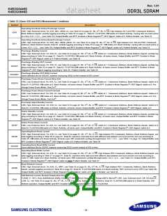
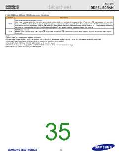
- "Basic IDD and IDDQ Measurement Conditions" are described in Table 33
- Detailed IDD and IDDQ Measurement-Loop Patterns are described in Table 32 on page 31 through Table 39.
- IDD Measurements are done after properly initializing the DDR3 SDRAM. This includes but is not limited to setting
RON = RZQ/7 (34 Ohm in MR1);
Qoff = 0B (Output Buffer enabled in MR1);
RTT_Nom = RZQ/6 (40 Ohm in MR1);
RTT_Wr = RZQ/2 (120 Ohm in MR2);
TDQS Feature disabled in MR1
- Attention : The IDD and IDDQ Measurement-Loop Patterns need to be executed at least one time before actual IDD or IDDQ measurement is started.
- Define D = {CS, RAS, CAS, WE} := {HIGH, LOW, LOW, LOW}
- Define D = {CS, RAS, CAS, WE} := {HIGH, HIGH, HIGH, HIGH}
- RESET Stable time is : During a Cold Bood RESET (Initialization), current reading is valid once power is stable and RESET has been LOW for 1ms;
During Warm Boot RESET(while operating), current reading is valid after RESET has been LOW for 200ns + tRFC
[ Table 32 ] Timing used for IDD and IDDQ Measured - Loop Patterns
DDR3-800
DDR3-1066
DDR3-1333
DDR3-1600
Parameter Bin
tCKmin(IDD)
Unit
6-6-6
2.5
6
7-7-7
1.875
7
9-9-9
1.5
9
11-11-11
1.25
11
ns
CL(IDD)
nCK
nCK
nCK
nCK
nCK
nCK
nCK
nCK
nCK
nCK
nCK
nCK
nCK
nCK
tRCDmin(IDD)
tRCmin(IDD)
tRASmin(IDD)
tRPmin(IDD)
6
7
9
11
21
15
6
27
20
7
33
24
9
39
28
11
x4/x8
x16
16
20
4
20
27
4
20
30
4
24
tFAW(IDD)
tRRD(IDD)
32
x4/x8
x16
5
4
6
5
6
tRFC(IDD) - 512Mb
tRFC(IDD) - 1Gb
tRFC(IDD) - 2Gb
tRFC(IDD) - 4Gb
tRFC(IDD) - 8Gb
36
44
64
120
140
48
59
86
160
187
60
74
107
200
234
72
88
128
240
280
- 32 -

 SAMSUNG [ SAMSUNG ]