Audio ICs
BA6820F / BA6822S / BA6822F
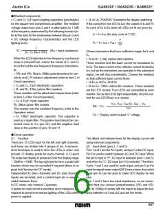
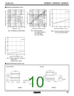
(3) Peak hold
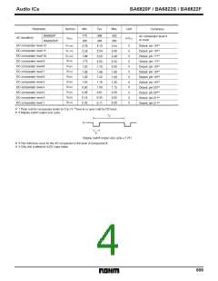
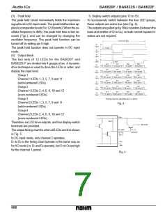
(1) Display switch outputs (pins 12 to 15)
To successively switch between the four LED groups,
these outputs are active low (see Fig. 4).
The peak hold circuit momentarily holds the maximum
signal level in AC input mode. The peak hold function ap-
pliestocomparatorlevels5to12(8points). Whentheos-
cillator frequency is 4kHz, the peak hold time is two se-
conds (Typ.), and can be changed by changing the
oscillator frequency. The peak hold function can be
turned off by setting pin 8 high.
Theoutputsarepulledupby36kΩ resistors(betweenthe
base and emitter of Q1 to Q4), so leak current bypass re-
sistors are not required.
The peak hold function does not operate in DC input
mode.
(4) Output block
The two sets of 12 LEDs for the BA6820F and
BA6822S/F are divided into 4 groups of six. A dynamic-
drive technique is used to drive the LEDs in order, and
display the input level.
Group 1
Channel 1 LEDs 1, 3, 5, 7, 9 and 11
(odd-numbered LEDs)
Group 2
Channel 1 LEDs 2, 4, 6, 8, 10 and 12
(even-numbered LEDs)
Group 3
Channel 2 LEDs 1, 3, 5, 7, 9 and 11
(odd-numbered LEDs)
Group 4
Channel 2 LEDs 2, 4, 6, 8, 10 and 12
(even-numbered LEDs)
Therefore, six LED drive outputs, and four display switch
terminals are provided.
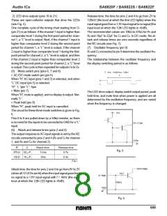
The output timing chart for when all LEDs are lit is shown
in Fig. 3.
In DC input mode, only channel 2 operates.
D1 to D4 in the timing chart operate in the same way as
forACmode(i.e. D1 andD2 operate), butO1 toO6 arehigh
for the channel 1 period.
668

 ROHM [ ROHM ]